• Please be sure to read the rules and adhere to them. Some banned members have complained that they are not spammers. But they spammed us. Some even tried to redirect our members to other forums. Duh. Be smart. Read the rules and adhere to them and we will all get along just fine. Cheers. :beer: Link to the rules: https://www.forumsforums.com/threads/forum-rules-info.2974/

542 Cab Forward Restoration

GMoose

Well-known member
GOLD Site Supporter
…… hello G,... yes, the 1010 is one of the rare engines , that all 4 sleeves are attached to the top plate ,... when we did ours, we had a hell of a time getting them out, pretty sure it hadn't been apart before,.... I was actually asking about the engine you had hanging off the loader ….:thumbup:

The engine out of the cat is a Jeep Tornado 230. It has an overhead cam with only 6 lobes. Each lobe runs both the intake and exhaust valves. The Pistons are domed, some have called it one of the first hemi engines, but I am not sure if it is. I think there are some photos of the engine torn apart on the first page of this thread. I have the machining complete on the engine, this winter I will be putting it together, I will post that process when I start working on it.
 

GMoose

Well-known member
GOLD Site Supporter
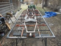
Frame is done for now, all welding is complete. Welded in new perimeter of the bed and new cross supports. Welded original stake pockets and tie hooks back on. Weld on new front fifth wheel supports. Beefed up welds on engine mounts and transmission mounts. Repaired miscellaneous frame damage. Yes, I am tired of welding, went through about 15 pounds of wire, a bottle of purge gas, and probably a dozen cut off wheels and misc. grinding wheels.

Here it is all tacked together, ready for welding:

DSCN3793.jpg

Bottom view, welding complete:

DSCN3821.jpg

Top view, welding complete:

DSCN3853.jpg

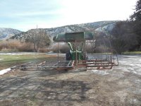
Using the JD 1010 to move the frame for the winter, next spring/summer I will finish anything that needs cleaned up or modified, then sand blast and paint.

DSCN3856.jpg

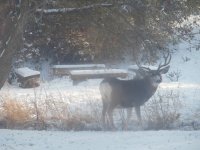
And here is the visitor we had this week in the back yard, just behind the snowcat:

DSCN3761.jpg
 

GMoose

Well-known member
GOLD Site Supporter
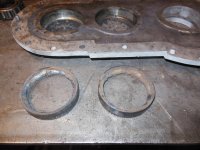
Worked on the transfer case a bit also this weekend. Got the two bearing races out of the lower half of the case. I had heard of the weld bead on the face of the race trick but had never tried it. So I tried it on these two races, two beads later, one on top of the other, and the races came right out. Great trick. New bearings and seals should be here in a week or two. This will give time to complete the tool I am fabricating to adjust the preload rings, and clean everything up for reassembly.

DSCN3763.jpg

DSCN3768.jpg
 

GMoose

Well-known member
GOLD Site Supporter
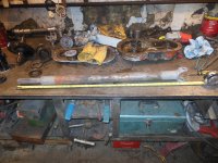
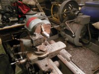
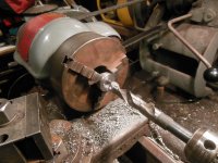
Started cleaning up the drivelines, the front one is damaged. Took it to the driveline shop in town, which I found is now permanently closed. So, I guess I will either replace the tube myself or have my machinist friend do it for me. Looks like it will just barely fit in my Lathe, but I have no way of chucking up the U-joint end. Will figure something out.

DSCN3770.jpg

DSCN3772.jpg

DSCN3786.jpg
 

GMoose

Well-known member
GOLD Site Supporter
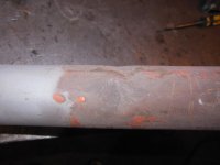
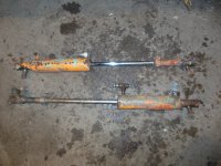
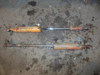
Tore the hydraulic cylinders apart to see what we have. Appears the rear cylinder has been rebuilt once. It has a newer lip seal for the shaft seal, the seal in the body is what looks like piston rings, and it appears the shaft has been re-chromed. Also, this cylinder has a spacer (about 2" long) that fits down in the barrel to limit travel. Other than that the cylinders are the same with the same part number stamped on the barrels.

Looks like new seals all around, and will look into having both rods re-chromed.

Top is rear cylinder
Bottom is front cylinder:

DSCN3799.jpg

End ball joints:

DSCN3802.jpg

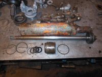
Rear cylinder, spacer is on right near end of shaft:

DSCN3804.jpg

Front cylinder:

DSCN3806.jpg
 

GMoose

Well-known member
GOLD Site Supporter
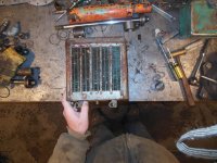
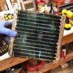
Tore the heater apart so I can take the heater core in for flush, checkout, and repair if necessary. Also going to take the radiator in at the same time.

Didn't get a picture of the heater core once it was out, but I have this:

DSCN3811.jpg

DSCN3815.jpg
 

olympicorange

Active member
Started cleaning up the drivelines, the front one is damaged. Took it to the driveline shop in town, which I found is now permanently closed. So, I guess I will either replace the tube myself or have my machinist friend do it for me. Looks like it will just barely fit in my Lathe, but I have no way of chucking up the U-joint end. Will figure something out.

View attachment 119203

View attachment 119204

View attachment 119205


… GM,.. the good thing about the driveshaft ends, is that they have a shoulder to slip tube onto . most of your u-joint ends usually have a ''dimple'' for the lathe pointer to set into , to set up. if yours doesn't , you may have to find center and set your own....
 

GMoose

Well-known member
GOLD Site Supporter
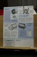
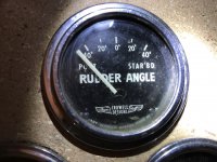
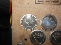
Need some help from anyone that may be into boating out there. The rear fifth wheel has a rudder angle gauge since the front and rear turn independently of one another. I have the gauge, but the sending unit is missing. I know I can get a newer one, however if at all possible I would like to find one like the original. The brand is Crowell Designs, here is an image of the gauge and sending unit (upper left corner of brochure). If not able to find a sender, just the technical information, such as what ohm range and angle it sweeps through, would be helpful.

If you have any suggestions on a brand and/or model for replacement sending unit that I can use with this gauge, that would also be helpful.

Also, in the next couple of weeks I will get this thread caught up, have made a lot of progress (meaning have spent a ton of time and $$$) lately.

Rudder Gauge.jpg
 

Track Addict

Bronze Member
GOLD Site Supporter
VDO makes a sending unit that should would.

Faria makes a gauge that is close.

Check with vetus also.
 

sno-drifter

Bronze Member
GOLD Site Supporter
Need some help from anyone that may be into boating out there. The rear fifth wheel has a rudder angle gauge since the front and rear turn independently of one another. I have the gauge, but the sending unit is missing. I know I can get a newer one, however if at all possible I would like to find one like the original. The brand is Crowell Designs, here is an image of the gauge and sending unit (upper left corner of brochure). If not able to find a sender, just the technical information, such as what ohm range and angle it sweeps through, would be helpful.

If you have any suggestions on a brand and/or model for replacement sending unit that I can use with this gauge, that would also be helpful.

Also, in the next couple of weeks I will get this thread caught up, have made a lot of progress (meaning have spent a ton of time and $$$) lately.

View attachment 120488

Here is a gauge factory installed in Tucker.
 

Attachments

  • Rudder angle gauge.jpg
    Rudder angle gauge.jpg
    99.5 KB · Views: 390

Mill666er

Active member
SUPER Site Supporter
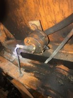
My 542 has ‘side companion steering’ but did not come with a rudder gauge. I picked up a cheap one from eBay not knowing if I could make it work. It was a challenge to figure out how to mount the sending unit and had to mount the gauge upside down for it to correct. The range is 0-190 ohm

6827f9a19a55014ed132d0a73ee76363.jpg


1f956b4927a97fc63c00ad6f3790caae.jpg


c3880dc8dcbf47878bec5bfd0ae884a5.jpg
 

GMoose

Well-known member
GOLD Site Supporter
Thank you very very much for all the help and info from everyone, especially mill666er, for the photos of the sender unit attached. Here is what my 542 came with, a guage, a bracket, a wire, and a hole in the top of the 5th wheel. I should be able to get this feature working with the information and contacts everyone has provided. If anyone else has photos of the sender unit attachment that would be great.

Thanks again, your help is much appreciated!!!


Here is my gauge, obviously.

DSCN4008.jpg

If you look close you can see the small hole in the top of the 5th wheel next to the trunion pin, where I believe the original sender unit arm was attached.

DSCN2918.jpg

Here is the bracket and wire. On the bracket you can see the outline (missing paint) of the original sending unit. It was mounted the same as Mill666er's is, facing down.

DSCN0643.jpg
 

Backyardski

BackyardskiLima
GOLD Site Supporter
The rear fifth wheel has a rudder angle gauge since the front and rear turn independently of one another.

I’m not familiar with how they operate independently. Does the orbital valve not control front and rear cylinders together? Or does it just end up getting a little out of wack because they aren’t mechanically tied together? How do you make the adjustments to correct? Are you able to crab steer? That could help walk it out of a trouble spot if so. Hmmmmm.
 

Track Addict

Bronze Member
GOLD Site Supporter
Also curious as to why the rear would be independent of the front. Trail packing is all that comes to mind. One pass 4 track widths.
 

Pontoon Princess

Cattitute
GOLD Site Supporter
I’m not familiar with how they operate independently. Does the orbital valve not control front and rear cylinders together? Or does it just end up getting a little out of wack because they aren’t mechanically tied together? How do you make the adjustments to correct? Are you able to crab steer? That could help walk it out of a trouble spot if so. Hmmmmm.

Steering wheel operated only the front pontoons, while a lever between the front seats controlled the rear pontoons, and let your imagination run wild with all the moves like Jaeger you can do.

merry christmas
 

GMoose

Well-known member
GOLD Site Supporter
I’m not familiar with how they operate independently. Does the orbital valve not control front and rear cylinders together? Or does it just end up getting a little out of wack because they aren’t mechanically tied together? How do you make the adjustments to correct? Are you able to crab steer? That could help walk it out of a trouble spot if so. Hmmmmm.

I have found two different steering setups for the snow compactor configuration. There is a patent for the steering configuration. I don't have the number with me right now, I will post later. However, my understanding of how this configuration works is when the manual valve is activated both front and rear pontoons steer by use of the orbital valve (steering wheel). This system uses 1 orbital valve, 2 flow diverters, 1 hydraulic lock, and 2 Rams. My 542SC has one less flow diverter and is plumbed differently. The rear ram for the rear pontoons will not steer with the steering wheel, they only steer by activating the rear valve one direction or the other. I will draw up a schematic of both systems and post it in the near future.
 

sno-drifter

Bronze Member
GOLD Site Supporter
Here is the factory installed rudder indicator Mr. Moose. The fun part of driving one of these SC machines is that the hyd. lever for steering the rear axle is mounted with the lever moving fore and aft. Why not have it move right and left? Another Sno-Cat mystery.
 

Attachments

  • Rudder angle sender.jpg
    Rudder angle sender.jpg
    92.1 KB · Views: 322

Backyardski

BackyardskiLima
GOLD Site Supporter
I have found two different steering setups for the snow compactor configuration. There is a patent for the steering configuration. I don't have the number with me right now, I will post later. However, my understanding of how this configuration works is when the manual valve is activated both front and rear pontoons steer by use of the orbital valve (steering wheel). This system uses 1 orbital valve, 2 flow diverters, 1 hydraulic lock, and 2 Rams. My 542SC has one less flow diverter and is plumbed differently. The rear ram for the rear pontoons will not steer with the steering wheel, they only steer by activating the rear valve one direction or the other. I will draw up a schematic of both systems and post it in the near future.

I’m interested in seeing how that is set up. I have a skytrak rough terrain forklift that has selectable steering- front wheel, four wheel and crab, and I never gave much thought as to how this was accomplished. Maybe they borrowed tucker technology.Thanks for sharing the info!
 

Cidertom

Chionophile
GOLD Site Supporter
If you want difficult to troubleshoot steering, Pierce Fire Apparatus had the patent (I think). High speed rear axle is locked strait. at low speed between certain steering angles it steers in direction of turn and at really low speeds and large angles it counter steers. I think they finally took out the auto counter steering.
 

Logger1965

Active member
GOLD Site Supporter
Sounds like steering a log trailer. Try explaining that to someone who doesn't understand a pole steered trailer.
 

GMoose

Well-known member
GOLD Site Supporter
Off work for 2 weeks, will try to get the thread up to date.

Back to the rams, all rebuilt now.

Here are the before pictures, top ram is the rear, bottom ram is the front:

DSCN3799.jpg
 

GMoose

Well-known member
GOLD Site Supporter
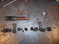
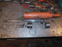
Here they are disassembled:

This photo is of the bottom ram. Both the rear and front rams are the same model, however the rear one has a travel limiter sleeve (bottom right) installed in the barrel, about 2 inches long.

DSCN3804.jpg

Front ram disassembled:

DSCN3806.jpg

You can also see that the ball joint springs are broken, had to replace all four (2 per ram, 1 per end). Pricey little things, $15 each.

DSCN3802.jpg
 

GMoose

Well-known member
GOLD Site Supporter
One of the cones which sit in the base of the ball joint housing had been cut down about an 1/8", this required the adjusting screw on the end to travel to deep into the thread. This set the cotter pin to high to lock into the slot of the plug. So, I build a new plug, hopefully this does not screw up some alignment when I assemble back onto the frame.

DSCN3880.jpg

DSCN3881.jpg
 
Top