• Please be sure to read the rules and adhere to them. Some banned members have complained that they are not spammers. But they spammed us. Some even tried to redirect our members to other forums. Duh. Be smart. Read the rules and adhere to them and we will all get along just fine. Cheers. :beer: Link to the rules: https://www.forumsforums.com/threads/forum-rules-info.2974/

Tucker 1544 IRAN Project

Blackfoot Tucker

Well-known member
GOLD Site Supporter
Perhaps I should add some background about Scott’s attitude regarding bending fuel lines.

When I got the 1544, the steel fuel line from the fuel pump to the engine was not in great shape. It looked like a previous owner had tried some modifications by hand, and without tools, and that almost always results in a lousy outcome. There was an in-line filter between the fuel pump and carburetor, which was probably Chrysler’s design. But Tucker installs a filter before the fuel pump, so is that second filter really necessary? I didn’t think so and it makes the path of the fuel line longer. So my thought was let’s replace the stock fuel line with a new one and eliminate the inline filter. Scott then bent a new line. I’ll call that “Line 1”. I’m not sure why, but somewhere along the line it became necessary to bend another line and I’ll call that “Line 2”. While Scott is a fan of fuel injection, a big fan, actually, and the fuel injection system would REQUIRE new fuel lines, he drew a line and said "I’m not bending any more”. And unlike Obama’s famous line in the sand (that wasn’t), Scott stuck to his refusal.

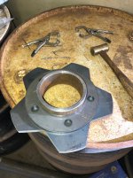
Here’s a pic of Line 2 that was removed as part of the fuel injection installation. We need a moment of silence for this now removed artifact. If you think this is a big deal about nothin’... I can’t disagree.

IMG_3313.jpeg


As I already mentioned, a previous owner had Bubba and Billy Bob install a radio/CD player in the dash. I’m not sure which previous owner decided they needed a master disconnect electrical switch, but there was one of those, too. A great big rotary switch mounted above the instrument panel and being fed with seriously large electrical cables. Why? I mean having a master disconnect isn't a bad idea, but putting it there? I wanted to remove it, and…you guessed it... Scott didn’t.

We unbolted the instrument panel and Scott removed the radio/CD player and its wiring. I started the process of removing the disconnect switch. Scott was done before I was, and when I pulled the electrical cables from inside the cab I saw the red cable, with full battery amperage available, had exposed wire. I showed the exposed wire to Scott as further justification to eliminate the master disconnect, and he said he had seen that. One of the power wires for the radio/CD player was connected there. Unbelievable.... More Bubba and Billy Bob buffoonery.

IMG_3315.jpeg


Reading ahead on the Edelbrock installation instructions there is a very prominent warning about using an ignition coil that meets certain parameters, or severe damage to the ECU could result. One might think that with such consequences, and Edelbrock’s claim of “This kit includes everything you need for a hassle-free installation" that one would be supplied. Well, you might think that, but you’d be wrong. They provided a list of suggested ignition coils, and doing a little research I learned that ignition coils are typically oil filled, but for applications where increased vibration is likely, an epoxy filled coil is better. If you’ve ever been in a rubber belted Tucker on a hard surface, you are very familiar with vibration…. I ordered an epoxy filled coil.

We started the process of removing the superfluous wires and components I mentioned above and integrating the new Edelbrock wiring harness and the ECU (aka: computer). Right now it looks like a complete mess, but that’s basically the sausage making process as we get everything cleaned up and put together. To give Tucker some credit, in 1986 it looks like they’d made a change (or a previous owner upgraded the system) to using the Weather Pack system of electrical connection. We used this same system on Thundercat and CHUGSzilla, so we’re familiar with it, and like it. There are some special tools and a special crimper, but if you have those on hand (we do) it’s quite easy to work with. If you've tried working with the proprietary connectors on new vehicles (the Chrysler family's seem to be the worst) than you know how aggravating they can be. The Weather Pack system is much, much easier to work with!

We have a Tucker electrical schematic from 1978/1979, and unfortunately it doesn’t match the 1986 era wiring, but it is somewhat helpful, and we’ve been referring to that as we work our way through this. We strongly prefer not having to splice wires to extend them, but you have to work with what you have, and unfortunately we have to do that. We try hard to use the same color wires, or as close to that as we can, but sometimes it’s just not possible. For example, the Tucker harness had a blue wire with yellow spiral tracer that ran from the ignition coil to the tachometer. The Edelbrock harness had roughly a 6” long smaller gauge brown tachometer wire that would have to be lengthened by about six feet. We scrounged through our assortment of wires and found a very slightly larger gauge wire in a brown color that’s quite close. That will run all the way to the tachometer. Our objective is to make the harness as consistent as possible, and in a logical and easy-to-follow sequence. Unfortunately, the Tucker harness has some running splices (meaning an inline splice where a second wire is attached (essentially piggybacked) to the the first wire), and the second wire is a different color. Then that connection is buried in the harness. It makes tracing electrical issues orders of magnitude more difficult if there are future problems and one doesn’t have a schematic to reference.

It seems Tucker makes one harness that has provisions for various options. If a customer ordered the machine with them, then those wires would be used. If the options weren’t ordered, the wires are there, but not hooked up. There are wires run to a location for a relay, but since the option(s) weren’t ordered there is no relay in that location. We will leave that part of the system intact. It does give a future owner the possibility of installing the related option, or re-purposing those wires for another function.

Unfortunately, I can see someone cussing us out at some future date, but we are doing the best we can. Hopefully, that cussing will be minimal, and well in the future….

Yesterday, Mother Nature gave us a friendly reminder winter is fast approaching...we had some snow flurries at home.
 

Blackfoot Tucker

Well-known member
GOLD Site Supporter
When I bought my snow-trac it had the wire feeding the ignition switch fed by a #10 sheet metal screw through the battery cable.
CT,

It's truly amazing what gems of creative buffoonery are found on snowcats. It's one thing to make a field repair to get something out of the back country. But then you properly address the underlying problem, and don't call the Band Aid fix "good enough".

I'm going to paraphrase a comment from a flight instructor I saw: "Never underestimate what a low-functioning mechanic can pull off in a spectacular fashion."
 

Logger1965

Active member
GOLD Site Supporter
Leaning slightly on electrical, I still believe I have seen the best one yet. A 1342 I had died and wouldn't start, tearing up distributor cap/rotor, hmmmm? Further looking discovered someone had broken plastic gear on the bottom of distributor shaft where roll pin secures it and had fixed it by putting a zip tie around it to hold it in place!!! Brush fix, they had used a bright green tie maybe red or blue would have lasted longer till I was farther away from home hence requiring a longer walk home in the dark.
 

Blackfoot Tucker

Well-known member
GOLD Site Supporter
Leaning slightly on electrical, I still believe I have seen the best one yet. A 1342 I had died and wouldn't start, tearing up distributor cap/rotor, hmmmm? Further looking discovered someone had broken plastic gear on the bottom of distributor shaft where roll pin secures it and had fixed it by putting a zip tie around it to hold it in place!!! Brush fix, they had used a bright green tie maybe red or blue would have lasted longer till I was farther away from home hence requiring a longer walk home in the dark.
Wow!

I must admit using a zip tie for that purpose never would have even crossed my mind. I never watched the MacGyver TV show when it was on, and I'm not sure the inspiration it provided has turned out to be a good thing. For some people? Absolutely. But for others? Decidedly not!
 

Blackfoot Tucker

Well-known member
GOLD Site Supporter
I forgot I had taken this pic, but it does an excellent job of illustrating both problems I described. You can quite easily see there is no way to get that bolt in the hole and lined up perpendicularly with the cylinder head for it to thread in to the tapped hole. Note, though this seems pretty obvious, grasping this not-so-difficult concept is beyond Edelbrock’s comprehension. It makes one wonder “If they can’t even do this right, how well will the fuel injection system work”? You can also see how the casting bulges out to accommodate the fuel injectors and there’s no room for the valve cover flange. Again…pretty simple, and as I questioned in my earlier post, how difficult would it have been to fix these issues when the casting is already being machined on CNC equipment?

IMG_3395.jpeg


Now back to wiring….

Here’s a pic of the instrument panel as modified by Bubba and Billy Bob. If you’re wondering why the fan switch is different than the other rocker switches, that’s a question for Tucker. It is a two position switch (high and low speeds) which in switch vernacular is called a single pole, double throw. The other switches are on-off, and are single pole, single throw.

IMG_3409.jpeg


Our layout is a bit different, and the CAD file has been sent to Streamworks for the new water jet cut instrument panel. We adjusted the gauge and switch positions slightly, and then played around with some different design layouts. If you look at the hole for the ignition switch, you’ll see that it’s round. The actual ignition switch has two flats on the sides so when it’s installed, it can’t turn even if someone turns the key with considerable force. Having a panel water jet cut allows one to have the hole cut with flat sides. Yes, a small detail, but why not do it right when you so easily can?

The rocker switches will be in two rows of three switches with two blank switch cover plates in each row. (On Thundercat we used a rocker switch for the wiper switch function but making that setup work properly required Scott’s electrical knowledge and the addition of some diodes. It took a fair bit of time to figure out how to make that work, and then get everything properly wired and soldered.)

And what I described as "sausage making”. We use white electrical tape and I write semi-legibly the function of each wire. We’re trying to label all the wires which will help when the new switches are installed.

IMG_3411.jpeg


If you look at the transmission shifter, just beyond that you can see the hole for the master disconnect switch we removed. It has a mate over on the right side of the dash where someone had installed a cigar lighter. Scott will weld a patch in both holes and he’ll weld up five other smaller holes. The dash will then be repainted.
 

Snowy Rivers

Well-known member
Looking great....
Water jet cutters are the catsazz .....No warping of the material and tolerances can be held very close..

I had the center plates for the new wheels on my cat water jet cut........

Gonna be sweet.....
 

Blackfoot Tucker

Well-known member
GOLD Site Supporter
Looking great....
Water jet cutters are the catsazz .....No warping of the material and tolerances can be held very close..

I had the center plates for the new wheels on my cat water jet cut........

Gonna be sweet.....
Snowy,

Completely agree about water jet cutting. The company we use, StreamWorks, are easy to work with, they do a great job, and the cost is reasonable. The price to have them supply the 1/8” thick aluminum panel and then cut it to our specifications is $115. The time it would take to very accurately lay out all the holes manually would be lengthy, and then trying to cut everything precisely would be time consuming, too. The reality is the accuracy provided by StreamWorks is better than we could do. To be blunt; it’s a bargain.

I can’t remember the last time I used that word about anything snowcat related….
 

Blackfoot Tucker

Well-known member
GOLD Site Supporter
Before installing the new aluminum instrument panel we needed to get the steel dash panel taken care of. In my last post I mentioned a hole on the far side of the shifter that needed to be addressed... and then stupidly forgot to post the picture. Here's that missing pic.

IMG_3412.jpeg


Scott welded up all the holes in the dash and we removed the shifter and the data plate. The entire panel was sanded, a bit of filler was used to smooth out the areas where the holes were welded, then the dash was primed and painted. Tucker’s official color is ”Omaha Orange”. Okay, but what’s the correct paint code for Omaha Orange? I reached out to our own beloved Pontoon Princess, a true champion of Omaha Orange, and she said there are multiple versions of the color, and there is not a single correct paint code. Great… just Great!

I went to the local Sherwin Williams Automotive paint store in SLC and was literally blown away by the great customer service. I was up front that I wasn’t buying multiple gallons of their top-of-the-line Genesis paint (thousands of dollars), but rather I needed only to paint the dash panel on a snowcat, and I explained the quandary on getting the color right. The young man, Jantzen, offered to take his computerized color matching camera out to the 1544 (maybe five miles away at Scott's shop) take some photos and get the best match he could. And he did exactly that... and he brought some polish to get the existing paint looking as good as possible before he took the photos. He mixed up a small amount of paint according to the system and made a spray out card for me. It looked fantastic. We discussed paint options, and his recommendation based on product quality and cost was Sherwin Williams Sunfire Pro Urethane Single Stage paint. The overall value received for the dollars spent was truly excellent. This was the fifth automotive paint store I’ve bought from in SLC, and I have found my go-to supplier!

The paint sprayed quite nicely. It didn’t cover all that well so Scott (who does the spraying) put on a fairly light first coat. Then we’d wait 10-15 minutes and apply another coat. Four coats total, and the dash panel looks pretty nice, and from a couple of knuckleheads, no less.

After looking at how the dash turned out, my thought was this: The Infamous WBJ1 could have had a beautiful Omaha Orange custom Tucker…. but NO. He went with the hideous green he chose. Had JC Penny met The Infamous WBJ1 first, he never would have said “The customer is always right”.

In addition to the 1544 we’re trying to finish up CHUGSzilla, and that’s our top priority....
 

YamaDooPolCat

Well-known member
SUPER Site Supporter
Any chance you could get the paint mix the shop used?
I get spray cans of Omaha Orange made up as I need them, but they never quite match. Maybe because the quantity I need is so small?
Thanks.
 

chowderman

Well-known member
there's a 'system' - Pantone matching - the swatches look like:
1699553507683.jpeg


if you eyeball match to the Omaha Orange (of your choice....) - any paint shop can match it 'by the numbers'
and repeat it exactly next year . . .
 

Blackfoot Tucker

Well-known member
GOLD Site Supporter
Any chance you could get the paint mix the shop used?
I get spray cans of Omaha Orange made up as I need them, but they never quite match. Maybe because the quantity I need is so small?
Thanks.
Sure,

The paint code is SUS - 105479176 - F.

But, that’s a Sherwin William specific code. It’s called AGR Orange, but that's a Sherwin Williams name. They have a color book, and the reference number is 18S0908, which is how you'd find the color in the book, and that is also a Sherwin Williams color book. The bottom line is this info may be helpful at a Sherwin Williams Automotive paint store, but pretty much useless anywhere else.

Also, your orange may be different, and from my conversation with Pontoon Princess - it probably is.

Truthfully, our 1544 Tucker project needs a complete repaint. A previous owner painted it, and they did a less-than-optimal job. The color they used was orange, but not Omaha Orange. Paint is flaking off the hood, and off the roof. It looks pretty bad. When we decided to replace the instrument panel with a new one, and install new switches, it wouldn't have looked right new to the steel dash panel with some scratched paint and a bunch of extra holes. We (really more me than Scott) decided to fix the steel dash panel and then repaint it. We had to start somewhere with the color, and we started with the custom matched Sherwin Williams paint. We do not plan on repainting the machine before selling it, but we’ll give the new owner the small can of residual paint we used. They can then choose to get more of the same for a full repaint, or do something else.

My first Tucker I had repainted before I sold it. It was a mediocre at best paint job: a complete exterior repaint, but not very detailed, though it wasn’t expensive, either. For example the driveshafts were painted in place. Yeah, well not much paint made it onto the top of the driveshafts, so when the machine was moving the driveshafts looked striped.
The second Tucker was one we re-cabbed, and that got a complete repaint of the interior and exterior. It turned out very nicely.

DSC01656.JPG
 

DAVENET

Bronze Member
GOLD Site Supporter
Also, your orange may be different, and from my conversation with Pontoon Princess - it probably is.

Very true. My local shop we use at work works with DuPont. The OO code thru them is N2053H. I'm very happy with it, but it does appear to have a slightly more red tint than the1969 OEM paint.
 

Snowy Rivers

Well-known member
The water jet is just awesome ...
When I did the "Snowflakes" (Wheel centers) for my cat....the parts had to look good and be clean....
Also I wanted the center pilot hole to be a slip fit onto the hubs.....
No machining on the pilot holes.

I grabbed the part in the lathe by the pilot hole and machined the "Flakes" so the center could just tap into the wheel rims SNUG....
Set up a drill fixture using the center from an old well used two piece 2100 steel wheel....
This got a good hole pattern on a "Drill jig only snow flake"
Then a fresh snowflake was placed on a pilot tool ( Ring that bolts to the mill table) and the dedicated drill jig on top.

Fasten the entire setup to the table and transfer the hole locations...

With the drilling assembly under the spindle it was a simple task to drill a hole...rotate the part and index the next hole and so on.

Then countersink the holes at 60 degrees for the lug nuts....

The alloy wheel hub type assemblies are sweet....The cost was waaaaaaaaay off the charts as far as budget goes.

The wheels are off the shelf stuff but came with 5 x 4.5 (Cat uses 5 x 5.5)
Cut the centers loose and toss them....Clean up the rim....Fit the new 3/8" plate centers using an offset jig made using and original steel wheel as a guide....
Weld the centers in....

The original wheels were stamped steel and prone to the lug areas collapsing when tightened repeatedly.

Also the side loading from the BIG AZZ tracks was hell on wheels....
The 57" tracks were bad...the 6 footers were off the charts....

The cast alloy wheel hub combos really are nice....
I have those for the two fronts and rears
Some horse trades and a bit of luck scored these..

Without the water jet cut parts....This would have been much harder to do.
Not impossible .....Just way more work to hold tolerance.

The end results were very nice with run out quite good enough for the slow speed these turn.

The offset tool is a McGyver ....But puts the plate center where it needs to be...

Locate...Tack weld.....Finish weld...Clean up and paint....
The 3/8" plate is not going to bend.....If it does...other stuff gonna really hurt...
 

Attachments

  • Countersunk holes.jpg
    Countersunk holes.jpg
    310.4 KB · Views: 22
  • Center offset gauge.jpg
    Center offset gauge.jpg
    371.4 KB · Views: 25
  • Locating jig 1.jpg
    Locating jig 1.jpg
    306.6 KB · Views: 20
  • All welded up.jpg
    All welded up.jpg
    362.6 KB · Views: 23
  • New wheel2.jpg
    New wheel2.jpg
    187.6 KB · Views: 18
  • New wheel3.jpg
    New wheel3.jpg
    296 KB · Views: 24
  • New wheels1.jpg
    New wheels1.jpg
    291.4 KB · Views: 22
  • Drill jig with pilot.jpg
    Drill jig with pilot.jpg
    396.1 KB · Views: 25

Blackfoot Tucker

Well-known member
GOLD Site Supporter
Scott and I have been doing general wiring clean up and integrating the Edelbrock ProFlo 4 fuel injection harness with the Tucker harness. We like the concept of neat and orderly wiring, with wire bundles covered with nylon split loom (nylon has higher temperature tolerance than less expensive polyethylene split loom).

The Edelbrock harness has some wires that are too short for our installation, and others that are nonsensically long. For example, the wires running to the coolant temperature sensor are about 18” longer than those running to the throttle position sensor, yet they're only about 8” apart. Many of the wires were run in non-split plastic tubing and Edelbrock used a cloth electrical tape. We removed just about all of the cloth tape, and most of the plastic tubing, so we could organize the wires in a manner we think looks a lot better. In many cases this meant folding wires back over themselves in a bundle to shorten their effective length. A sequential multi-port fuel injection system has individual fuel injectors, and they each need wires running to them. You can, I suppose, just use the Edelbrock harness as it comes out of the box, but that would mean wire bundles exposed in a somewhat haphazard manner, and coils of excess wire laying around. Functionally - fine, but cosmetically - bleccch. By spending the time, admittedly multiple hours, and some money on supplies, we’ll hopefully make it look as though it was a factory installation.

Previously, I have been able to buy different size split loom from NAPA at reasonable prices. But for some reason their selection was pretty much non-existent, and what they had was way over priced. So, I ordered several sizes from Amazon... and of course we’d have way more than we need. When it finally arrived (Yes, that’s meant as a slam on what has become of Amazon’s once excellent “Prime” delivery service) ... most of it was just cr*p.

I had ordered five sizes, four of which were Electriduct brand. All four were basically unusable. Split loom needs to be flexible. Scott and I have installed quite a bit of the stuff, and what we got from Amazon was extremely stiff and totally inflexible. Scott commented that the split loom was so stiff and sharp he was concerned he would cut his hands as he tried to feed wires into the split loom - and Scott doesn’t have soft skin on his hands; it's more like, well, gorilla hide. The defective split loom went back to Amazon, and new stuff was ordered from a different supplier.

The Tucker general wiring layout changed from the 1980 system in Thundercat and CHUGSzilla to the 1986 design in the 1544. Previously, Tucker installed relays in the same location as the self re-setting circuit breakers and bus bars. Now, they have one relay in that location and others mounted on the firewall. We added relays to both locations. A relay for the front roof mounted LED light bar by the CBs and bus bars, and the new fuel pump relay and an Edelbrock harness relay on the firewall. We also changed out the original horn relay to a Bosch style relay. The old one was working fine, but if/when it failed a replacement would be harder to find. Bosch style relays are very commonly available. Admittedly, not a big deal, but trying to be proactive for the future owner.

The new instrument panel is ready for installation. After picking it up from StreamWorks I took it to a local powder coater, and he got it done in a few days. We were ready to start the process of installing the gauges and new switches but some bonehead (that would be me) forgot the heat shrink tubing at home. Instead, we made up the hard steel fuel line from the pressure regulator forward and the steel vacuum line that runs from the pressure regulator to the throttle body. Both lines need to be finished where they connect to the engine. We’ll use a 12” length of braided stainless steel hose with crimped-on female AN fittings for fuel, and some rubber vacuum line tubing.

Prior to installing the existing gauges into the new instrument panel we put some duct tape on the dash panel and steering column to protect them from scratches and Scott bent some pieces of aluminum sheet to hold the instrument panel as it was assembled.

Here's a pic. You can see the dash panel sporting it's new Omaha Orange paint, and the new instrument panel is on the passenger seat. Note the bent aluminum pieces that support the instrument panel when it's being assembled.

IMG_0013.jpeg


The new split loom arrived and it’s nice and flexible. When I find a supplier with quality products at reasonable pricing, I like to pass on the name of the company to help others. The vendor I bought the split loom from is called elecdirect.com. They had a good selection of split loom at reasonable prices, and the shipping cost was reasonable, too. They’ve earned the coveted BFT endorsement!

Bottom line: Progress continues, albeit slowly… as is our style.
 

Blackfoot Tucker

Well-known member
GOLD Site Supporter
We finished installing the new switches in the new instrument panel, and getting everything wired up. With Thundercat and CHUGSzilla we installed the individual wire's crimp-on terminals directly to the switches.

To refresh memories, here's a before pic of the dash and instrument panel. Note the goofy master switch and the holes to the right of the switch.

IMG_3291.jpeg


Carling (the switch manufacturer) makes terminal connector housings that use Packard 630 terminals. The advantage is you can remove all the wires at once from the switch, and the individual wires and their terminals are retained in the housing. We decided to try this system on the 1544, and of course the Packard terminals require a different crimping tool. Now, after competing the switch wiring process, we won’t do it this way again. As the saying goes “The juice just isn’t worth the squeeze”.

The connector housings are fairly cheap, as are the Packard 630 terminals, but they’re a bit more difficult to assemble. As I’ve described, the new switches are illuminated, and the wiring for the switch lighting requires daisy-chaining lots of wires and using short lengths of wire as jumpers. This usually means putting two wires together in one terminal, and the Packard 630 terminals are more difficult to do this with. After the terminals are crimped we use a heat gun on short lengths of 4:1 heat shrink tubing which covers the crimp section of the terminal as well as a short length of the wire(s). If you have to remove a Packard 630 terminal from the housing, it's a definite PITA. We have the Delphi WeatherPack tools and one of those is used to release a tab on the Packard 630 terminal to remove it from the connector housing, but it’s a frustrating task, and a task you simply don’t have if you skip the connector housings. (With no plans to use them again, I now have "a lifetime supply" of Packard 630 terminals….)

Of the six switches we installed, five are fairly simple single pole, single throw switches; the proverbial on-off switch. You have a power wire to the switch and a wire to the accessory. Easy-peazy. Having the switch backlighting requires more wires; three more to be exact. Two are ground wires and one is a power wire. These can be daisy chained from one switch to another as well as between terminals on the same switch. But you can see adding the backlighting functions we like adds to the work of wiring a SPST switch.

But the one single pole, double throw switch (on-off-on) for the heater fan with high and low speeds, is more complicated. Instead of five total wires on the switch, you have seven; three for the switch function, and four for the backlighting. Except, to get the backlighting logic working correctly, you need to add two diodes to the backlighting power wires. Diodes allow current flow in only one direction, an electrical check valve, so to speak. They are quite small, and that means for reliability they really should be soldered to wires as opposed to just using crimp terminals.

Here are a couple pics of the repaired and repainted dash panel as well as the new instrument panel. For some reason Tucker dash panels seem to be a magnet for people to install various things on. We wanted to bring the dash panel back to it's original clean, functional, and unmolested look.

IMG_0035.jpeg


IMG_0036.jpeg


We also installed a new LED parking brake warning light, as well as new push-pull cables for both heater temperature and heat/defrost functions. The Carling switches are available with backlighting in different colors. For Thundercat we went with (The Green Tucker Mafia will love this) green, The Infamous WBJ1 chose amber for CHUGSzilla and for the 1544 we went with blue. Thundercat’s gauges have green LED bulbs to backlight the gauges, and we installed new blue LED bulbs in the 1544’s gauges. We think it’s a sharp look…and definitely superior to…green.

And after all that talk about switches, back lighting and lighting logic, here are a couple pics with all the switches on. The angle I took the pics at as well as the ambient shop lighting and the dome light somewhat drown out the backlighting of the gauges. The hour meter does not have internal lighting but all the other gauges do,

IMG_0037.jpeg


IMG_0038.jpeg


After completing a sub-project, one often thinks back: Was it worth it? I seem to have an unerring ability to underestimate how much time something will take. And despite having completed two other complete instrument panels not all that long ago, I underestimated the time involved…bigly.

Now it's back to other things. The LED dome lights I bought from Amazon turned out to be unsatisfactory, so I've ordered others that we know will work, though they come with incandescent bulbs. Installing those will complete the wiring on the project.
 

Cidertom

Chionophile
GOLD Site Supporter
Beautiful work. I do like the 630 where there is environmental considerations. I agree they are a PITA, but some places that are wet, salty, exposed....
 

Blackfoot Tucker

Well-known member
GOLD Site Supporter
Thanks everyone for the kind words….

PP,

I hope Scott doesn’t see that.

His head is big enough already. The other night he said "Did I ever tell you how good I am?” (Gee, not much self-promotion in that statement.) I of course responded with “Yes. Every chance you get.” But you get an idea of the back and forth banter…. In the interest of accuracy - he really is the brains and talent in our projects.

CT,

I’ll try to remember to bring the Packard 630 terminals to SV2024. It’s great that you’ll be able to use them!

The Infamous WBJ1,

As a founding member of the Green Tucker Mafia, your comment about green doesn’t surprise me in the least.

When working on snowcat projects The Gorilla seems to be the voice of the Green Tucker Mafia, getting in little pokes and jabs at every opportunity. Example: “Hey Scott, what color wire should we use for X?” His answer is always “green”, knowing full well that isn’t a viable answer. He says it only to be obnoxious…. in the best tradition of The Infamous WBJ1.
 

Blackfoot Tucker

Well-known member
GOLD Site Supporter
After completing the instrument panel installation we still needed to finish up the wiring to the new fuel pump, as well as some under-cab wiring cleanup. Scott and I have somewhat differing viewpoints on extra wires. He is light years ahead of me when it come to electrical system knowledge, so most of the time I just defer to his judgement. Being I suppose, an electrical simpleton I like one continuous wire from a switch to the powered accessory, which also means one color. It makes tracing things MUCH easier, at least it does to me. Of course, if you want to add something later it’s a not an insignificant amount of work to add that new wire all the way from switch to accessory, as well as a power wire to the switch. The 1544 had several wires in the harness that had no purpose. Scott wanted to leave them so at some future point an owner could tap into those and not have to run wires all the way, and that’s basically what we did. We also labeled some unused wires under the dash, and they too were left in position.

New split loom was installed all the way back to the fuel pump and the backup squawker. The existing split loom had been zip tied to various things along the way. We prefer stainless steel cushion clamps, also called Adel clamps, and we used those where we could in place of zip ties. The new fuel line is complete from tank to engine and that had to be secured to the frame in places, as did the new vacuum line from the fuel pressure regulator to the engine. We used more stainless steel cushion clamps as well as Scott’s beloved self-drilling TEK screws. I gotta admit, he is making me a believer in those…. We also had to use zip-ties where there was no access to install a cushion clamp. It would have been preferable to be able to install the cushion clamps uniformly in terms of distance between clamps, but with the engine and transmission installed, access is extremely limited, and it just wasn’t possible.

The new dome lights arrived and they have an on-off switch on the light. That meant soldering an additional wire to the dome lights integral switch, and this way the dome lights can be turned on by (1.) Opening the driver’s door, (2.) By activating the dome light switch on the instrument panel, or (3.) By turning on the switch on the dome light itself. Thundercat is a factory-four door model, and it came with a plate welded to a roof frame member for an optional rear dome light (that was not ordered). CHUGSzilla, a factory three-door machine, came with a rear dome light installed. Silly me, I made the mistake of assuming the 1544 would also have a rear plate for a dome light... but no. We do think having a dome light in the rear for passengers is a worthwhile feature, so we fabricated a plate and Scott welded it to the roof frame members, unfortunately burning some paint in the process. I have no clue why, but Tucker offsets the dome lights slightly to the driver’s side. We centered the new rear dome light in the new plate. Turning on either dome light's integral switch turns on both dome lights. To have them independent would have required adding diodes to the power wires, and we thought that feature wasn’t worth the trouble.

Here are some pics. The new front dome light.

IMG_0061 2.jpeg


And the rear dome light mounted to the new plate. If you’re thinking “Gee Blackfoot, that's some lousy looking upholstery”, I completely agree. But we’re trying to hold the line on project creep.

IMG_0062.jpeg


We’d been mulling over how to deal with the valve cover/Edelbrock intake manifold interference issue. We absolutely did not want to remove the intake manifold to do some machine work to the manifold on a milling machine, so that meant we’d have to work around the intake manifold’s issues. Thicker valve cover gaskets are available, but they aren’t significantly thicker. Double valve cover gaskets might work, but we weren’t confident they wouldn’t leak. Grinding/milling the vertical flange on the valve covers to clear the intake manifold bosses weakens the valve covers, and that flange also helps in sealing out liquids from getting underneath the gaskets to the top of the cylinder heads. Hmmm?

A fair bit of Googling turned up a product I’d never even heard of; valve cover spacers. Essentially spacer plates that are installed between the cylinder head and the valve covers. They’re made in different thicknesses and I ordered the 1/2” thick versions. Given the circumstances, we think this is the best option, but it’s frustrating to waste, yes that’s the right word, waste two hundred bucks due to Edelbrock’s poor design.

While we were waiting for the valve cover spacers to arrive we had some other tasks to accomplish:

Previously we had installed a new rear main seal on the engine. Well, we had an oil leak at the back of the engine so we thought there was a problem with the new seal. But changing that seal is difficult because the oil pan must be removed, and to do that the exhaust has to come off and the engine lifted. The crane in Scott’s shop came in very handy…again. (Note to self: When you build your dream garage/shop make sure there’s a bridge crane.) Instead of lifting the engine, we disconnected the front fifth wheel plate and trunnion assembly from the truss frame, and then lifted the front of the machine away from those. Almost easy-peazy. Reassembly required using a ratchet strap to pull the front fifth wheel plate/trunnion assembly into position. (I love that crane!)

We needed to weld a threaded collar, called a "bung”, to the exhaust pipe for the fuel injection system's oxygen sensor. Removing the exhaust system allowed us to position the oxygen sensor optimally, rather than just where we could get access to weld it in position. We did that while the exhaust was out for the oil leak repair.
So… once we had the oil pan removed it was obvious the culprit for the leak was not the rear main seal after all, but the oil pan itself. Still, we installed a new seal. The rear main bearing cap on the inside contains the rear main seal. On the outside, there is a machined groove that the rear molded rubber part of the oil pan gasket sits. The machine work on that groove was atrocious. Rather than a smoothly machined radius, it was segmented, and we thought that might very well be the causal factor for the leak. Scott liberally applied some Permatex RTV sealant in the segmented groove, hoping that would fill any voids not filled by the molded rubber gasket.

Progress continues....
 

Cidertom

Chionophile
GOLD Site Supporter
Just wondering, could have Edelbrock designed around a stud rather than bolt, but failed to mention that in the instructions? Looks like there would have been clearance to get the nut on.
 

Blackfoot Tucker

Well-known member
GOLD Site Supporter
Just wondering, could have Edelbrock designed around a stud rather than bolt, but failed to mention that in the instructions? Looks like there would have been clearance to get the nut on.
CT,

I usually write my posts as an email, then proof read and revise so it’s accurate, informative, and hopefully no spelling mistakes, etc. I almost always change some wording along the way.

I think in my original version of discussing the intake manifold bolt interference issue, I said something like “Scott is a truly crafty bastard and despite his McGyver skills we couldn’t come up with an alternative to using a carbide burr on the intake manifold to create adequate room to install the one bolt”. I meant “crafty bastard” as a compliment to his ingenuity, but I decided to remove it to be more polite. We literally tried everything we could think of. The Edelbrock ProFlo4 system is north of $2K and the casting was beautiful. I genuinely did not want to do anything to mar it in any way, and neither did Scott. For example, we tried one of us holding the intake manifold slightly away from the cylinder head while the other tried to thread the problematic bolt into the cylinder head, essentially creating the required clearance with the space between the cylinder head and the intake manifold. No Bueno. The opposite cylinder head is in the way

What also adds to the challenge is the intake manifold gaskets are in place on the cylinder heads. Edelbrock supplied an intake manifold gasket set. Typically intake manifold gasket sets have stamped gaskets for the cylinder head interface, and separate molded rubber pieces that go on top of the vertical walls at the ends of the lifter galley. Edelbrock didn’t include those but suggested using FIPG (Form In Place Gasket) typically RTV silicone. One had to be very careful in manipulating the intake manifold not to disturb the carefully applied FIPG before the intake manifold was properly aligned. During our various attempts we had to touch up the FIPG a few times.

If you think “Well why not install the stud in the cylinder head first”? The problem is the intake manifold must be properly aligned with the stud while it is being positioned. The opposite cylinder head prevents one from getting the intake manifold in that required alignment.

In retrospect, and in thinking about this while typing away at the computer, it might have been possible to remove the exhaust from the right side exhaust manifold, then remove the right side exhaust manifold, loosen the alternator and remove the alternator and belt, then loosen all the right side rocker arms, remove all the right side push rods. unbolt and remove the right side cylinder head. Then one could install a stud in the problem area and slide the intake manifold in position. Then you’d have to reinstall all those parts with a new cylinder head gasket and a new exhaust manifold gasket. That might have worked. It would be a lot of ass-pain, and a few bucks, but the intake manifold would still be unmolested.The engine block has two hollow pins that the cylinder head sits on and I THINK you could slide the cylinder head in position and then it would drop over those. But sliding the heavy cylinder head across the new head gasket seems like a bad idea. If the head gasket doesn’t seal properly, you’ve got a lot of work to do to replace it. But honestly doesn't this seem a ridiculous series to hurdles to jump over because Edelbrock is too lazy and/or too profit conscious to fix a known issue?

And pity the poor guy who then has to remove the intake manifold (hopefully many years in the future). "How did those idiots install this thing?" I suppose Scott and I could be laughing from our graves…. Now if we knew the guy trying to remove the manifold was going to be The Infamous WBJ1? Yes Sir, we definitely would have gone that route (had we thought of it). We could even try and imitate his sinister MUAHAHAHA laugh!
 

Blackfoot Tucker

Well-known member
GOLD Site Supporter
After getting everything put back together with a new Mobil One oil filter and a new fill of synthetic oil, we had to wait a few days for the valve cover spacers.

In terms of installation we used one set of valve cover gaskets between the spacers and the cylinder heads, and a second set of gaskets between the spacers and the valve covers. I was underwhelmed with the seller, Medice Manufacturing. The spacers themselves are fine, but I think they’re overpriced and the customer service policy has a “Heads we win, tails you lose” feeling about it. For example, when I opened the package there was a piece of paper that said if one wanted to return the item there would be "at least a 25% re-stocking fee". The spacers supposedly come with bolts and washers…except they didn’t. Really? You don’t win many friends or much repeat business that way. Scott and I chatted a bit about them and if we had it to do over again I think we’d try and draw the spacers on his cad system and get StreamWorks to water jet cut them for us. They’re really just pieces of flat aluminum plate cut to fit the shape of the cylinder head where the valve cover mates, along with holes for valve cover bolts.

The best way to install the spacers, the multiple gaskets and the valve covers would be to use studs instead of bolts. Medice offers a stud kit, but the price is a ridiculous $50, for 10 studs and nuts… plus shipping. We took some 2 1/2” long 1/4-20 bolts and cut the heads off. Then threaded them into the cylinder head and used those as alignment pins to get everything in position. Then we removed the pins individually and installed 1 1/2” long stainless steel socket head cap screws and stainless steel AN washers.

The stock air cleaner assembly was not going to be re used and the replacement I bought looks really nice. Re using the stamped steel valve covers would be perfectly functional, but in comparison to the new air cleaner and the new aluminum intake manifold I thought they would look out of place. Cast aluminum valve covers were the order of the day. The updated engine won’t just run well, it will look good, too!

The throttle linkage mechanism on the throttle body contacts the air cleaner base so we’ll install an aluminum spacer to raise the air cleaner base. There is an air temperature sensor for the fuel injection system, and that’s been installed in the air cleaner base.

Once all the mechanical and electrical connections are complete you download an app to your phone (or other device). You choose one the engine profile that most closely matches the configuration of your specific engine. In our case the engine is bone stock except for a Hughes Engines' camshaft. That particular grind just barely moves the engine from “stock” to “mild”. We set up the fuel pressure regulator at 58 psi and the Edelbrock system came with 35 lb/hour fuel injectors. Once those parameters are selected you upload the profile to the computer (mounted in our case on the firewall) via Bluetooth. You turn the key and then it’s a bit anti-climactic. The engine starts and runs not very well at first, but the system is learning and the engine needs to come up to temperature. You can see all the measured parameters on the phone such as engine RPM, timing advance, water temperature, etc. The next time we started it the engine ran noticeably smoother. We did all this before before we had the throttle cable hooked up or the hand throttle or automatic transmission kick down installed. The as-modified-by-Tucker bracket will not fit on the new intake manifold so Scott did some cutting and welding to modify it further. There are six intake manifold bolts on each side of the manifold. The original installation used bolts four and five, and we’re using five and six. We have to remove the distributor to install the bracket, and then reinstall the distributor. I brought the bracket home for some cosmetic refinement.

We probably have one, possibly two, more nights of work to finish things up, and of course we have to wait for the air cleaner spacer. But we’re close.

I think it’s fair to say we’ve never thought that engine ran “well”. It ran “okay”, but not really any better than that. Starting always seemed to be an event, in one way or another. While we have precious little run time on the engine with the Edelbrock system, initial impressions are encouraging. I will say the Walbro electric fuel pump is an obnoxiously loud unit.

I wish I had some photos to share but I wanted to post the information anyway because right now (through 12/25/23) Edelbrock is running a 10% off sale on some products and ProFlo 4 systems are included. I have a non-Tucker project vehicle that will use a Ford 460 engine and I decided to purchase a ProFlo 4 system for that engine and take advantage of the sale price. (Note: looking at photos of that system there are no intake manifold bolt interference issues, and it doesn't look like the injector bosses will require valve cover spacers!)

There are lots of different companies that carry Edelbrock parts, but I’ve been particularly impressed with Mammoth Racing in California. They've earned the "BFT Endorsement".
 

YamaDooPolCat

Well-known member
SUPER Site Supporter
When I first started my 318 after installing the Holley Sniper and electronic distributor, it ran terrible as well, and never got better. Finally figured out the Sniper had a bad circuit board and would not read the O2 sensor. The retailer send me a new Sniper and then it would read the O2 sensor.

After that your experience with start up was similar to mine. But my 318 would suddenly stop or try to die or stumble ready bad. Found out the EFI was picking up stay induced signals from a part of the wiring harness that was laying across the ignition coil. I removed that part of the wiring and the Sniper learned quickly and runs great.

So yesterday I decided to treat the engine to a new coil. Pertronics 45001 for more spark.


IMG_5481.jpeg
 

Blackfoot Tucker

Well-known member
GOLD Site Supporter
Of course the holidays always slow our progress, and this year was no exception. However, I have a small lathe and a mill at our other place and I brought snowcat stuff for each machine to work on. The lift cylinder on Chugszilla’s six-way blade has clevis ends. One end is a casting and the other end is welded. The welded end was too thick to fit into the mount on the blade frame. Scott was ready to break out his angle grinder and a cut off wheel, but I thought “Hey, I’ve got a milling machine and I can use that and make a nice job of it”. So that was one project.

The 1544’s air cleaner spacer had a machined shoulder really made to use with a stamped steel air cleaner rather than the cast aluminum one we’re using That required some lathe work to remove the shoulder for our needs. The plan was to remove the shoulder and then weld the spacer to the air cleaner base. The spacer is also machined for a rubber O-ring to use as a seal to the carburetor/throttle body. Definitely a nicer setup than the standard paper gasket….

I’ll admit it can be hard to justify the expense of such equipment, but there is considerable satisfaction and pride in being able to do the work yourself rather than taking parts to a machine shop and paying them a bunch for them to do it. The latter is probably less expensive, but not much joy in that. It also seems you drop the parts off at a machine shop (trip 1) and return when they’re supposed to be done (trip 2) only to be told they’re not done and you have to come back again (trip 3). Having the tools to do it yourself reduces the hassle factor - which is an added benefit. Let's be honest, these snowcat projects pretty much never "pencil out" as far as economic viability anyway.

After removing the shoulder Scott welded the spacer to the air cleaner base and we finished that installation. We also completed hooking everything up to the throttle linkage on the throttle body. We may have some more tweaking/adjusting to do there to ensure everything is working okay. The 1544 gets parked outside Scott’s shop and then it's moved in and out to work on it. We had previously removed the front driveshaft and Scott attaches a nylon strap to the rear pintle hitch and uses one of his forklifts to lift the rear tracks off the ground and move the snowcat in and out of his shop. Last night we reinstalled the front driveshaft and it moved under its own power for the first time in months!

At this point we have some minor adjustments to make, some clean up inside the machine where we’ve been storing all kinds of fuel injection/wiring/etc tools and parts. Then it’s just about ready to take out for testing. I’ve been promising pics for a while….

Here they are.

Left side view of the completed installation.

IMG_0113.jpeg


A view showing the location of the "computer" mounted to the firewall below the red caution label. As previously mentioned, we tried to integrate the Edelbrock harness with the Tucker harness to make it look better. It's all hidden inside the nylon split loom.

IMG_0112.jpeg


A pic showing the infamous valve cover spacers.

IMG_0114.jpeg


A view of the right side. The first and last pics show the relocated fuel crossover line between the fuel rails. I mentioned this before also but relocating the crossover to the front allowed us to connect the fuel supply line at the right rear. We think it makes for a cleaner installation. You've already got heater hoses and a pretty large wire bundle in the split loom headed to the alternator and other electrical accessories. Adding a fuel line as well as a fuel pressure sensor and a wire to that sensor would make that location pretty crowded.

IMG_0117.jpeg
 

Cidertom

Chionophile
GOLD Site Supporter
Having your own lathe-mill-?? also means when you find out you need a couple more thousandths off it not as big of a pain. (Operative words : as BIG of a pain)
 
Top