Try as I may, try as I might, this year I will lose the fight. Yet again. But, I do believe I'm at better than 80% full completion. I could easily just throw it on the snow and run it, but where it will live makes it difficult to do quick or repetitive repairs. So I would rather just have it right coming out of the gate. Next summer/fall will be loaded up running down the check list of crap I've removed/replaced/added, but haven't been able to test. I'm praying there aren't a ton of wormholes I have to work thru between motor electricals/upgrades, dash electricals/upgrades. I suck at electrical, so I'm praying my notes, labels, drawings, rewiring was all good (even though I triple checked because it is my nemesis). Track adjustment will be needed- at least for one. Three came apart and were reassembled in the exact same order so 'should' be close. The first one I did was a complete breakdown all at once. It WILL have issues with adjustment fitting in the sprocket correctly. Hydraulics are all dry other than holding oil in the pump & orbital. Was originally shit-canning the drag valve and plumbing, but that changed a couple weeks ago. Valve was reworked and now deciding if I'm going to bother with the hoses. Don't really feel like incurring the cost of 4 new ones, but kind of pointless when a 30/yo hose pops first trip out.This thing hitting the local testing grounds this year?

-
Please be sure to read the rules and adhere to them. Some banned members have complained that they are not spammers. But they spammed us. Some even tried to redirect our members to other forums. Duh. Be smart. Read the rules and adhere to them and we will all get along just fine. Cheers. :beer: Link to the rules: https://www.forumsforums.com/threads/forum-rules-info.2974/
You are using an out of date browser. It may not display this or other websites correctly.
You should upgrade or use an alternative browser.
You should upgrade or use an alternative browser.
442 Refurbishment Project
- Thread starter DAVENET
- Start date


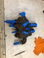


I would replace everything on the steering and return lines. The remote lines to rear you could reuse if your not using implement and remove the lever for safety.
Um, yeah. That was the plan.  But that scoundrel rodent from Wisconsin was heading east with a mostly open trailer and twisted my little finger to fill it. I was going to go electric like you did, but this one would be cost prohibitive to change to all elec. to work right. Everything is there already and has worked for 50 years. So screw it - put it back the way it was!
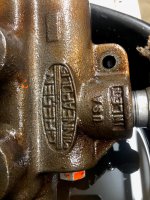
Just waiting on a photo of the OEM levers before cutting the floor and mounting the valve. Mine only had a single lever when I got it and it was heavily modified, leading me to believe it wasn't that way to start with.
But that scoundrel rodent from Wisconsin was heading east with a mostly open trailer and twisted my little finger to fill it. I was going to go electric like you did, but this one would be cost prohibitive to change to all elec. to work right. Everything is there already and has worked for 50 years. So screw it - put it back the way it was! Just waiting on a photo of the OEM levers before cutting the floor and mounting the valve. Mine only had a single lever when I got it and it was heavily modified, leading me to believe it wasn't that way to start with.
I have that setup with levers sitting in my garage with hoses. Out of the 442.
Should be the same setup. Was headed to sit in Thornton
Should be the same setup. Was headed to sit in Thornton
They look smaller here.


Groomer operator hat on.:Those are much smaller, and more in line with what I would have expected. My handle is home made to reach out in front of the seat instead of between them. No idea why they got rid of the second one.
if they were not needing it. and someone was riding shot-gun. that handle creates quite a bruise.
If the operator ran solo, coming up to roads and drive-ways needing to butter the snow out of the drag to create that perfect ribbon is an art. one bump of the wrong stick makes a speed bump of snow and back you go to smooth it out. after about 100 turn arounds that hitch stick has to go. In our case one stick is the hitch, the other wheels.
Happy to. It was headed north waiting for a new use better than sitting in my garage.
The 69 down back has a setup also I believe.
The 69 down back has a setup also I believe.
") All I need are the levers and the links/pins. Thornton would probably benefit from the valve body though
All I need are the levers and the links/pins. Thornton would probably benefit from the valve body thoughYup take what you need. Around anytime!
Levers have been placed under the Christmas tree for this project!
Sno will be in the stockings hopefully…..
Sno will be in the stockings hopefully…..


Was hoping the rear wasn't going to be as bad as the front. Yeah. Not as many parts, so not as much work, but work none the less. Nice hydraulic hose spring bushings . . .
Attachments


Amdiesel
New member
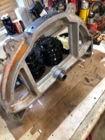
Are guys replacing the bushings in the mounts or replacing with a pillow block bearing and a set screw? I’m in the middle of doing new tie rod ends on my 1542, I went with both of the meritor p/n and had to cut them down about 3/4” to sit all of the way into the tie rod to line up correct. But while removing the rear rod I found a 1/8” gap in between the bushing and the mount. I’m trying to get ahead of this and not have any issues as I’m taking it to cat clowder in February which is about a 17hr drive so I’m trying to cover all the bases to avoid a crippling break down on the trails. Now after seeing these posts I’m going to pull the whole steering swing arm out and inspect for cracks. My cat has 5600hrs and 22k miles so god only know what it’s been through out there.The steering swing arm was getting blasted anyway for cleanup, but glad to have seen 1BG and track attics pod on cracking. Mine will definitely need Some tender loving care before repaint and install. Obviously a shitty repair the first time around which failed a second time. Even the hole in the bushing was installed 90° off in the top pivot and is completely cracked.
I didn't post a pic of them pressed in, but the number I needed was #6338K482 from McMaster Carr. I did have to turn down the inner shaft surface because the bushings come thru square and where the shaft of the swing frame meets is radiused.
Definitely take the time to get that blasted and inspect it closely. And then make sure if a repair is done, it is done correctly for the material it's made of. No welder will assume it is structural T1 / A514 and will weld it improperly like my first repair was done.
Definitely take the time to get that blasted and inspect it closely. And then make sure if a repair is done, it is done correctly for the material it's made of. No welder will assume it is structural T1 / A514 and will weld it improperly like my first repair was done.
Attachments

Amdiesel
New member
I appreciate that! I own my own diesel and heavy equipment repair and fab shop so Iv got everything to do the repair. Mine wasn’t cast like yours but I did a repair close to yours. Sand blasted, Ground the cracks and welded. Then plated the 3 sides and welded all of that in too. This was pretty much the end result.I didn't post a pic of them pressed in, but the number I needed was #6338K482 from McMaster Carr. I did have to turn down the inner shaft surface because the bushings come thru square and where the shaft of the swing frame meets is radiused.
Definitely take the time to get that blasted and inspect it closely. And then make sure if a repair is done, it is done correctly for the material it's made of. No welder will assume it is structural T1 / A514 and will weld it improperly like my first repair was done.
Attachments

All sorts of 'hackage' on the rear table. Cobbed in collar spacers for bearings, threaded bolts w/ some of the thread turned down for the collars to roll on, no way to get grease to them, etc., etc. Since the holes in the table had already been enlarged to take the larger bolts on the left & right, we just turned the bolts down for a smooth surface and machined new rollers to fit them and inside the guide channels. Also added grease ports. The channels were distorted on the top from carrying the weight, so we removed them (HUGE steel/alum. pain in the ass to get unthreaded) and flipped 180* to the flat side.
Attachments
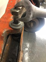


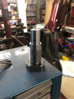

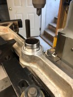
With all of the wear and wobbling on the outside edges, of course the pivot point wearing all wonky. It had probably 1/32 to 1/16" play when moving fore & aft. No need to do the other stuff if it was still going to be moving all over the place. Pete (master machinist buddy) has been making everything round again and is in the process of cutting a top-hat sleeve to take up the gap between the two to fit into the 'cup'. It also needs to raise the upper plate back up .093 from frictional wear due to excessive greasing ") . You can see how badly pitted the post was in #33.
. You can see how badly pitted the post was in #33.
. You can see how badly pitted the post was in #33.Attachments


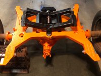
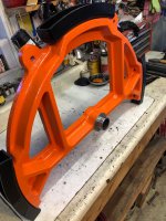
Finally back together. Springs re-arched and fresh bushings inserted. Just waiting on fresh bearings to get pressed back onto the axles before bolting the rear-end back onto the table. Should happen this weekend. A shit-ton of fixing to get everything back to turning in a level plane and to fix the spring wear in the table itself. Slides like two sticks of butter rubbed together now. May not have ever been this 'tight and level' in it's history?
Attachments


That closed rear Chanel is interesting. Wonder why they needed a stop like that?
Should be open and quite possible snow/ice builds up and prevents full swing on back but allows front which may equal bad?
Should be open and quite possible snow/ice builds up and prevents full swing on back but allows front which may equal bad?
Honestly I thought they were all like that? It should allow full turning potential, as is, I would imagine. The two outside roller bolts had been replaced after the fact, but the rear center pin is stock and had no bending. Thinking about it now, the channel did not have any contact spot on those outside plates where the roller would have been hitting it. So, if it touched, it was minimal and not often. But they were arched up from carrying to much weight, so I flipped them in place to start with a fresh flat surface.
sledhead Ed
Member
Do you think the welded the plates on the end of the channel thinking it would keep the channel tight and not bending or flexing?


That's a one of a kind so far from what I have seen. Pivot set correctly then the tie rods and tables aligned should prevent it walking out.
Doing a turn back up hill grooming after coming down with equipment would add forces. Maybe that was the local upgrade/enhancement! Ed Gil himself.
Doing a turn back up hill grooming after coming down with equipment would add forces. Maybe that was the local upgrade/enhancement! Ed Gil himself.
I have never seen the channel with the end capped. That said, I did see a 500 machine with the roller on top of the channel. I don't know how long it ran like that before I got it. It required disassembling parts to get it back where it belonged. While the capping will add strength, proper operation of the machine should not require it. I would remove the end caps for the reason TA stated, given the wrong set of conditions of snow, temperatures, moisture content, etc.; snow packing could cause trouble which would not be evident until bad stuff happens. More likely situation, given you as operator, than the abuse condition.


Bennyboy1337
Active member
Looking clean. Did you have a spring shop punch out your leaves or add a new leave when you rebuilt them? Or did you just disassemble, blast, spray, add new bushings? I'm debating taking a leaf pack to my local spring shop and asking if they could refurbish them.Rear end bolted back in place and officially out of dry-dock, i.e., off the oak stands. End brackets cut off center channel.