Copy on the combustibles in the tub.
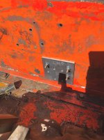
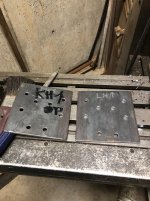
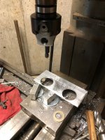
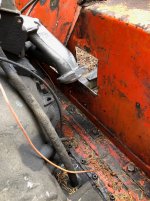
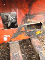
Today I welded the cover plate that had been under the disc brake on.
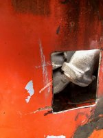
Sometime in the past somebody had cut two access holes in the floor of the tub and welded nuts on to bolt the plate covers in.
No way to get under the rig to get in there, and I do not have a service pit.
Decided to weld the covers on so they won't shake loose and get scraped off.
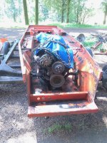
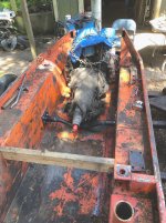
I got the tub clean now...
Not quite clean enough to paint, but the gunge is gone.....
Orange.
Serviceability is paramount.
There will no doubt be an item or two that will cause some issues when servicing....but I am trying hard to think through stuff and not end up building a BOAT IN A BASEMENT.
A couple issues.
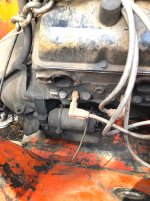
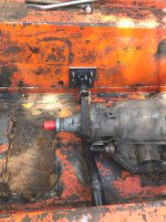
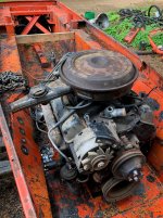
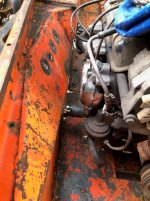
The starter.
Once the van goes on top it may be a booger......but there appears to be some access through the front wheel house openings and in through the front end.
Radiator will be up top in the van body so the area right in front of the engine will be open.
Some form of bolt on plate will likely be what covers the large opening in the tub where the original radiator was located.
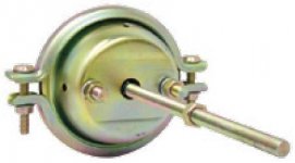
I am fiddling with several ideas for starters.
May try one of the little mini Denso starters.
Possibly construct a "Tool" to hold the starter up in place to allow the bolts to be installed.
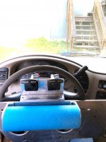
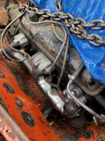
The transmission control is being a bit if a pain.
The Vans use a cable shifter that requires a special switch that bolts to the 4L60E trans to illuminate the shift quadrant in the dash..
The TH350 does not have any way to connect this stuff.
A stand alone floor type shifter with a cable seems to be the easiest solution....but the cable has to be installed on the trans. and then threaded into the vans operator area...
Looking into the idea of running the shift cable forward to a crank assembly with a rod running back to the trans.
Gotta make it easy to assemble and adjust.....
I looked at a couple of fully electronic shifters.....but they has a myriad of power/control wires and are very spendy....
It may come down to building a custom shifter from bits and pieces and mounting it on a bracket between the front seats.
There are two heat ducts between the seats and they are under the carpet.
The seats sit on a riser/stool and have plenty of material to mount a bracket on that can serve to mount shifters????????
The cable can go forward and out the cowl alongside the doghouse and then curve back towards the rear on the drivers side.
I really want to get a good plan hatched before the van is mounted....
I DO NOT want to be scratching my AZZ and looking at the thing UH DUHHHHH OH CHIT FRANK...
Some stuff is fairly straight forward.....but getting a reliable shifter has to be right on and not a sketchy maybe type thing..
I don't want crap that leaves me stranded some place.....
Wiring is more or less a NO BRAINER....Add length and connect the sensors and such that match the ones on the van engine to the 305 V8
Same with the starter wiring.
The throttle cable is another item that may end up being a booger.
Specialty throttle cables are available to connect most applications to just about whatever you can dream up.
The V8 will be nearly right below where the little V6 once sat....should be an easy go....SHOULD BE..

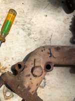
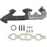
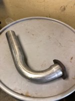
The exhaust is not gonna be tough....lottsa room for the pipe/mufflers.
Trans cooler lines are easy too...
Likely run braided hydraulic hose (Type with reusable field serviceable fittings)
Run them to a manifold near the front of the tub and then jumper to a cooler in the grille area....
Possibly use the stock cooler in the radiator, but I do like a stand alone oil cooler.....
These tend to cool better than running the oil through the hot water in the radiator.
OMG
All sorts of things to think about......
My kingdom for a good cad program .....