• Please be sure to read the rules and adhere to them. Some banned members have complained that they are not spammers. But they spammed us. Some even tried to redirect our members to other forums. Duh. Be smart. Read the rules and adhere to them and we will all get along just fine. Cheers. :beer: Link to the rules: https://www.forumsforums.com/threads/forum-rules-info.2974/

Astro van cat conversion

Snowy Rivers

Well-known member
Plan is coming together.
Got the ideas sketched out last night.....Scared up the pieces this morning and went to work on it...

Adjustable up and down as well as side to side a bit.

It feels good.....The steering joystick will be about where my hand is in the one piccy
Left hand can hold the steering wheel for driver stability....
 

Attachments

  • IMG_6166.jpg
    IMG_6166.jpg
    542 KB · Views: 57
  • IMG_6167.jpg
    IMG_6167.jpg
    335.7 KB · Views: 57
  • IMG_6168.jpg
    IMG_6168.jpg
    424.4 KB · Views: 56
  • IMG_6169.jpg
    IMG_6169.jpg
    367.9 KB · Views: 52

m1west

Well-known member
GOLD Site Supporter
when are you going to build the motor and trans, where you live you are going to run out of summer real fast.
 

Snowy Rivers

Well-known member
A few more pics
An access hole in the mounting plate to allow easy install/removal of the morse cable
The RED SPOT on the floor is about where the cable will penetrate .....

Looks like the stock cable that came with the shifter may work fine (LENGTH)
We have summer weather until late September here......I am about 20 miles south of Portland Oregon near the community of Newberg
Just north of HWY 99w

Not real worried about the engine right now....I want to get the cab mods/repairs done during the nice weather.
The tilt front end is gonna be a pretty good job......
Radiator mounting and such.

I do not want to pull the cabs off until the body work is complete.....A lot of work to remove and replace the bodies by myself....At least as far as getting them all lined back up....

The cat chassis ....Frame...axles and such are pretty well good to go....Need to put two more wheels together and get the last tires mounted....


Diffy is complete ....(Just need to put the axle tubes on and stuff the shafts in....
I do not want to be tripping over the beast as it is large when the axles are on.

I still need a few goodies for the engine.....We are getting there.

Once the cab and rear cabin are finished up they will be such that we can sit them aside and get the power pack done.

Tranny needs to be gone through.....TH350 IS AN EASY LITTLE BOX TO REBUILD..

Still thinking about going with a full manual valve body (Select shift) Where you put it is where it is.....

Much less hassle .....No worries with governors...shift points and all that.......With the low gears in these beasts.....The select shift is looking really good

The vortec heads are on my shelf all ready to go.....Modified for the big marine roller cam.....
This nice weather of late is nice to work in..
 

Attachments

  • IMG_6174.jpg
    IMG_6174.jpg
    287.7 KB · Views: 45
  • IMG_6172.jpg
    IMG_6172.jpg
    359.5 KB · Views: 43
  • IMG_6170.jpg
    IMG_6170.jpg
    333.9 KB · Views: 44

Snowy Rivers

Well-known member
Looking at orders that are inbound....Tracking shows the little arm rest is now in Los Angeles Ca.....
Not bad travel time as it was shipped from Bulgaria.......

Looking forward to getting that little jewel in my paws...I need to work out the mounting on the arm rest so the steering joystick can be mounted.

I do not want to toss any paint on the mounting rail assembly until all the goodies that end up being mounted on it are dealt with.....

Some stuff may be bolted....some things may wind up needing a bit of welding too....

The steel pop rivets showed up yesterday....Now the seat brackets can be fastened in permanently.....

A real shame that these rivets are not available locally......Sure seems like they should be.
I ordered up a new ignition key lock.... (Key was busted off in the one on the column....) Far easier to deal with this while the column is on the bench.....A good time to toss in a fresh ignition switch and a head light dimmer switch too......

We should be good for a long time on these switches.....The multi purpose switch mounting on the column is nice....Just not all that handy to get to ....might as well do it now......

Picked up a piece of aluminum plate to make a suitable cover for the old factory shifter hole in the tunnel....

Getting the cab ready to rock and roll is my priority at this time......
I want all the basic functions needed to operate the cat dealt with now.......NOT LATER trying to sort out stuff.

Steering controls and other non GM stuff that needs to be sorted out....
Adding in a batch of extra relays to run the steering valves and a few other things.....

Once the cab is done then it's on to getting the tilt front end done......I have never personally done a tilt front end.....seems like some basic fabricating 101 .....

I guess the bottom line is to be able to drop the fresh engine in and just hook stuff up.....
I really don't want to be sorting out a ton of crap after the engine is in.....
The engine mounts were tacked together back when I dropped the 305 SBC in a couple years ago.....So when things come apart the engine mount needs to be finish welded (Mounts are a universal set that is cut to fit, beat to suit and paint to match type of kit)

The 2100 tub has a deep sump under the engine that was set up for the deep oil pan on the 391 Ford V8.
This big sump in the belly has been modified by others (Read as BUTCHERED) and I want to clean things up and remove the unneeded lump hanging down under...

The new oil pan for the 406 is long and shallow with extra width on each side and baffles and gates to keep oil at the pump......Be fine for a cruiser......

Getting the belly cleaned up will be nice and be rid of the Butchery left by others.
These same folks cut two access panels in the belly to be able to service the tranny and other stuff...THESE THINGS ARE NO LONGER THERE.....At least not where the holes are of any use.

Going to weld the panels in permanent......

Far easier to just yank the cab and the power pack to work on stuff......The 2100 was a fully closed chassis/tub.......It has it's drawbacks...


Depending on just how all this shakes out.....I may make the area under the engine oil pan a bit different.....Still can't drain the oil easily......Suck it out with a suck pump ......Filter can be accessed but a bit difficult......A remote mounted filter is certainly on the table.......Just need to see where we can fit it so it is not a big azz mess when changing it..

An oil cooler may also be in the mix.....The early SBC usually did not have coolers......Would be easy to add one in front of the cooling stack.....

With most of the nick nack stuff dealt with.....Things should be able to fit back together like Legos.....

I am trying to avoid the boat in the basement thing.....

The aft cabin is pretty basic....A bit of wiring to get power and control to the door windows/locks ....Get the headliner, interior panels, seat and carpet back in.....The wiring for the rear lights (Stop, tail and turn) and the fuel tank sender feed are all in the rear body....Just need to use these as they are.

Feed for all the rear cabin electrical needs to be "Plug and play"......Make things easy to do removal of either cab/cabin
Several plugs that will only fit one way.....(All plugs different....7 pin...6 pin....4 pin and such.....a no brainer to connect them)

The Blazer had a trailer towing package....wiring is all in the body....Might be a good plan to connect it....Never know...

The one issue of possible difficulty as far as ease of disconnecting....Heater coolant flow.

The cabs being quite a bit higher than the engine could be a problem as far as flow.....Already decided to add a heater booster pump.....These are used on busses and other equipment.


Some disconnects with shut off valves to allow getting stuff apart with minimal green juice loss ????? still thinking on this one......There are options....I just don't want to deal with a mess if things need to come apart.

And so it goes......Fun stuff
 

Snowy Rivers

Well-known member
Did some research on disconnects for Glycol......CPVC seems common with hydronic heating systems....Glycol is usually run in these to prevent freeze up...

A few ball valves with common sized fittings could easily be arranged to allow connecting the dual heater system on the cat.
A set of disconnects at the return line from the front cabin heater heading aft to the rear heater and a set of valves in the rear as well.

Has anyone here worked with CPVC in hydronic heating.....???????

A lot of plastic fittings are used in the automotive industry to connect the heater systems.....

The goal is to be able to break these systems apart quickly and without a huge mess to deal with....Maybe a small amount of coolant loss the can be caught in a suitable can and put back in the system after any repair or need to remove either cabin.....

Sounds workable
 

Snowy Rivers

Well-known member
Got the seats back out of the cab and put the rivets in the seat brackets.

Good to go.....Got the BAD AZZ rivet tool after these steel rivets.....Still takes some ooooomph to get the 1/4" steel rivets set.

I taped a piece of paper across the factory shifter hole in the floor and copied the screw hole pattern.

Cut a piece of aluminum tread plate and drilled the holes.....Fits great....The outdoor cats and squirrels will not be back inside the cab now....

Seats back in and things ready now to get the column squared away and back in the cab.
A few of the switches are on order...Replacing the ignition switch, headlight dimmer switch and the wiper switch...
 

Attachments

  • IMG_6179.jpg
    IMG_6179.jpg
    381.6 KB · Views: 47
  • IMG_6180.jpg
    IMG_6180.jpg
    516 KB · Views: 45
  • IMG_6181.jpg
    IMG_6181.jpg
    566.2 KB · Views: 46
  • IMG_6182.jpg
    IMG_6182.jpg
    487.4 KB · Views: 44
  • IMG_6183.jpg
    IMG_6183.jpg
    618.2 KB · Views: 46
  • IMG_6184.jpg
    IMG_6184.jpg
    522.6 KB · Views: 48
  • IMG_6185.jpg
    IMG_6185.jpg
    485.3 KB · Views: 51
  • IMG_6186.jpg
    IMG_6186.jpg
    579.1 KB · Views: 46
  • IMG_6188.jpg
    IMG_6188.jpg
    625.2 KB · Views: 48
  • IMG_6189.jpg
    IMG_6189.jpg
    521.2 KB · Views: 45

Snowy Rivers

Well-known member
Checked parts arrival a bit ago.....The holiday messed things up a bit....The center arm rest to work in conjunction with the steering controls is in Portland this morning....Likely see it tomorrow.

The new switches will be along soon as well.

I think that today's task will be to get the Modified column currently in the cab removed and pave the way to install the one from the Blazer donor rig.....

We made a trip to the Bone yard yesterday afternoon to see if we could scare up any of the dash trim panels.

Sadly every single one there had been totally destroyed by hackers getting the tilt columns out.
Some folks only remove the bare minimums to get stuff apart....And destroy everything else...

The lower dash cover panel that goes below the steering column (Called the Vent panel on AC equipped rigs) seem to catch hell ....Screw holes broken out is common.....

The far left side is where the parking brake release handle is and getting that handle unhooked is not hard IF YOU KNOW HOW.....getting the panel off requires that handle be removed......

Most of the DIY crowd just rip the panel back out of the way to get a column out......


The one that came on the Blazer donor has several broken pieces where screws go......I have considered fixing with JB WELD to build back the parts broken off...

The part numbers are on the back of the panel......So far no luck in scarring up any NOS

Posted a Craig's list ad looking for a decent part.

This sort of stuff is not necessary to make things work.....But I would like the trim in the cab to be decent and not a rats nest....
Mix and match colors may well be the only way to piece things together.....

The cab was originally SADDLE color.....Same on the seats, dash, carpet, door panels, seat belts and headliner
The bucket seats from the donor rig are a bluish gray, dark gray carpet, black seat belts and the headliner is a dark gray.

The seat belts from the Blazer donor are in good shape.....The stuff in the single cab were trashed......

This thing is definitely gonna be a Calico Cat PUN INTENDED ....

Big issue is to have all the parts in and in good order......

At this late date there are a lot of parts that are simply tough to find (NOS)
The journey to find stuff is half the fun though.....

Mechanical stuff is easy.....
 

Attachments

  • Lower vent panel.jpg
    Lower vent panel.jpg
    397 KB · Views: 40

Snowy Rivers

Well-known member
Parts are showing up now.....Received the cool little arm rest that will work with the steering joystick .....

THE GOOD...THE BAD....THE UGLY.......The little padded part on top has a flip open lid and an adjustment to raise/lower the angle of the rest....Also the pad slides fore and aft a bit to give comfort options....

The entire unit is made of ABS plastic.....including the base assembly......The flimsy base is designed to flex over the center hump and fasten to the body......Arrrrrrgh.................Not gonna cut it....

The base fastens onto the box/pad portion and there is a bright light at the end of this tunnel......

Looks like a nice piece of 1/8" x 3 x 3" box tube with a 3/16" pad welded on one end will allow the arm rest portion to sit just perfect......The steel tube will slip into the rail that's already bolted the the floor..... Once that is situated it can be welded to the rail......Life should be good.

What looked great in pictures was not quite as grand in real life "Touchy feelie"
But it will end well I think....

More on that in a day or so with Pics too.

The new dimmer switch is here....along with the new ignition key cylinder/lock
The new ignition switch is still inbound.

Once I open up the column I want to complete the work in there and button it back up.....

So will wait until all the parts are here.....
 

Snowy Rivers

Well-known member
Got after the operators Arm rest today.....

I stripped off the plastic floor mounting brackets and tossed them in the trash.....Fabricated a steel bracket that welded to the rail in the floor.....

Did a test fitting....Looks great....

Tore the entire assembly out of the cab and welded the bracket to the rail....Entire unit back in now....FOR A BIT ANYWAY

The Steering Joystick mounting needs to be made and welded in.

Pics show a shot with the operators right arm on the rest and the hand like it would be holding the little joy stick.

A few other pics from various angles.
Tomorrow may be column day....All the parts are here now...I want that beast all repaired and in the cab.
 

Attachments

  • Arm rest1.jpg
    Arm rest1.jpg
    630.6 KB · Views: 38
  • Arm rest2.jpg
    Arm rest2.jpg
    587.5 KB · Views: 41
  • Arm rest3.jpg
    Arm rest3.jpg
    585.2 KB · Views: 41
  • Arm rest4.jpg
    Arm rest4.jpg
    612.5 KB · Views: 42
  • Arm rest5.jpg
    Arm rest5.jpg
    640.1 KB · Views: 43
  • Arm rest6.jpg
    Arm rest6.jpg
    678.4 KB · Views: 42
  • Arm rest7.jpg
    Arm rest7.jpg
    634.4 KB · Views: 42
  • Arm rest8.jpg
    Arm rest8.jpg
    491.6 KB · Views: 42
  • Arm rest9.jpg
    Arm rest9.jpg
    594 KB · Views: 41
  • Arm rest10.jpg
    Arm rest10.jpg
    532.3 KB · Views: 47
  • Arm rest11.jpg
    Arm rest11.jpg
    439.7 KB · Views: 43
  • Arm rest12.jpg
    Arm rest12.jpg
    610.1 KB · Views: 42
  • Arm rest13.jpg
    Arm rest13.jpg
    660.1 KB · Views: 43
  • Like
Reactions: PJL

Snowy Rivers

Well-known member
Started working on getting the new switches and such on the column......Stuck the column back in for a trial fit....

Looks great ....EXCEPT once the steering wheel is on the proximity to the shifter assembly makes operating the ignition key very very difficult.....I decided I am not going to fight that......
The issue is just my ability to turn my wrist while in the position to grasp the key.. (Stroke residuals)

Sooooooooooooooooo......We move the switch.....I picked up a heavy duty Pollak 4 position switch and it is going in a little bracket mounted to the lower part of the shifter assembly.....

The are a couple unused holes in that area of the shifter that need a job.....I got the bracket made and as soon as the switch gets here I will cut the half round hole to hold the switch....


I cut the wires loose from the OLD GM plugs on the sliding column switch and sorted that stuff out.

2 Red wires.....1 yellow....1 orange....1 brown....1 pink.....

I was able to find #12 wire in all colors But the PRETTY PINK....
It seemed smart to keep the stock colors so future work can rely on the colors meaning something.

There was really no reason to fight with the column switch as it's entire reason for being there was to allow the steering shaft lock......Since that is no longer of any importance.....MOVE THE SWITCH......

Pink wire ordered.....nobody local has #12 in pink or can get it either....


I could have used blue or white or ???? but decided to stay with factory so the schematic matches....

Added about 18" to all the wires (Waiting for pinky and the new switch...)
Will get that buttoned up ASAP.....

Have to replace the plug that goes from the column harness to the wiper harness....It had been thrashed.

I cut the one off the Blazer....Will connect it to the wire harness.......I do not want to get the column back in until PINKY is lengthened and the wires all routed out of the slot in the dash the column goes in...

There is a little storage tray below the dash for tossing stuff into....The end close to the column had a nice plastic end....Butched a hole through the tray to allow the wire bundle to sneak around the corner and connect to the new switch..

If things need working on It is a simple task to remove two 1/4" bolts holding the switch bracket and get it off the shifter....

Pretty much the operators work station will be easy to access all needed controls and all the gauges will be easy to see....
The heater controls are right close to the shifter...but easy to access......

The only area that is pretty much out of reach is the dash radio....No radio there.....May add an AM/FM with disc player later.

There are some options for a better location.....Will deal with this later......
The is a possibility of mounting a sound system on a bracket atop the shifter post.
Previous owners had chopped up the radio wiring pretty well.....So if we decide on tunes....we can wire things in clean and fresh.........
I have to replace the headliner anyway...there is a nice 4 speaker ABS plastic headliner kit available.

Will keep options open and not sweat it at this time.......
 

Snowy Rivers

Well-known member
More pics of the control layout...

I grabbed the auxiliary electrical box...(Rear door lock control and the large outside mirror control switch)

Some shots of the way things are coming together.
The little angle piece is the new ignition mount....Need to have the switch so I can machine the 1/2 round hole in the mounting and have it fit well
 

Attachments

  • control layout1.jpg
    control layout1.jpg
    499.5 KB · Views: 42
  • control layout2.jpg
    control layout2.jpg
    489.4 KB · Views: 44
  • control layout3.jpg
    control layout3.jpg
    465.8 KB · Views: 41
  • control layout4.jpg
    control layout4.jpg
    495.1 KB · Views: 42
  • control layout5.jpg
    control layout5.jpg
    454.1 KB · Views: 41
  • control layout6.jpg
    control layout6.jpg
    344.7 KB · Views: 39
  • control layout7..jpg
    control layout7..jpg
    501.3 KB · Views: 43
  • control layout8.jpg
    control layout8.jpg
    558.5 KB · Views: 42
  • control layout9.jpg
    control layout9.jpg
    531.1 KB · Views: 46
  • control layout10.jpg
    control layout10.jpg
    475.6 KB · Views: 43
  • control layout11.jpg
    control layout11.jpg
    472 KB · Views: 49
  • control layout12.jpg
    control layout12.jpg
    521.4 KB · Views: 42

Snowy Rivers

Well-known member
I stop and think about all the necessary engineering that goes into designing and building automobiles...trucks....SNOW CATS.....and such.

Entire systems that all have to fit together and function well (Supposed to anyway) and have aesthetic appeal to the end user.

Controls that do the job needed....are easy to access and comfortable for the operator all at the same time....

Then along comes some PUTZ (Like me) that says "Hell yeah" we can make this all work.........

You betcha red rider ......it will all work just fine.

A clean sheet of paper and everything all purposely placed to fit and function together well.....Great idea.....
The cost gets out of hand really quick......

Modifying an existing design can be fun.....but there is always a tradeoff somewhere or many of them.

One of my main areas that I am very anal about....I want things that may need to be accessed for serviced (In nasty conditions) to be easily accessible.....This tends to detract from aesthetics some...for sure....

I got an opportunity to get in the cab of a new Pisten Bully a while back......Absolutely marvelous layout.....Fit and finish was superb and controls were all placed where the operator can use them easily.......BUT COST $$$$$$$$$$$$$$$$

Meanwhile back at the ranch......Here we are at modify and make work headquarters......


I have been asked a few times over the past couple years about Why things are the way they are.

Answer.....The old 2100 chassis, although a good design for it's day....left a lot to be desired ....

Adapting the S10 has proven to be fairly easy.....But certain things such as engine location and getting controls to work...
Wiring is easy......Some mechanical connections like the transmission shifter....Awkward at best....Hence the cable arrangement ,,,,,And trying to keep the cable away from the hot exhaust ....2100 tub is tight.....even with the Chevy mouse motor.....

And the fun continues.

To look at things objectively..

Once the cab controls and wiring are done, the last of the mechanical stuff is a piece of cake (Tranny, drive shaft )


Sort of like Dr Frankenstein trying to graft a pig and a donkey together......Will it work.....Sort of....

Hence the term FRANKENCAT.....

A few other souls have done this swap with a 2100...."Dank Durango" and a fella that swapped a full size GM van

We all have our own ideas......and a budget to deal with.....

Big deal.....being able to duplicate or replace parts used to build the beast.......OFF THE SHELF TECHNOLOGY
 

Snowy Rivers

Well-known member
FINALLY

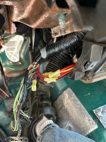
Found some auto wire with PINK insulation
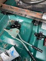
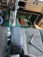
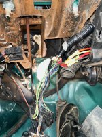
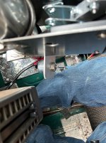
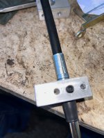
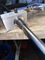
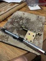
Finished up the Wire harness mods and got the bundle all taped up nicely....Still quite long ....Will cut to final length when we have the switch in hand........

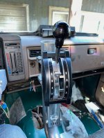
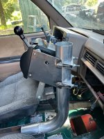
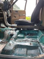
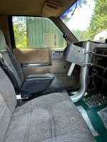
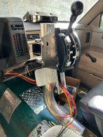
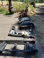
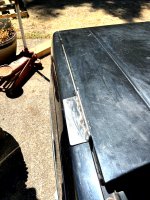
Getting the column back in is a royal PAIN IN THE AZZ.
A matter of getting the brake light switch out of the way so the column could slip in....Then put the switch back..
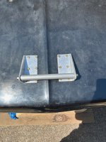
A single bolt.....Easy task....NO BLOOD LETTING

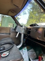
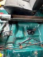
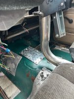
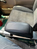
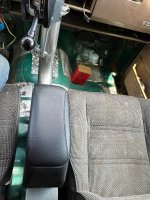
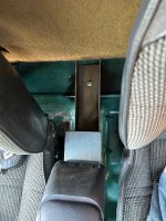
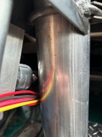
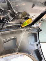
Wire harness all snuggled up in the tunnel area....

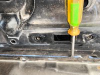
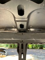
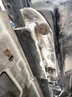
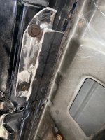
Seems that any under dash work always involves a BLOOD LETTING

All the metal under the dash area are always sharp as hell and it seems that one always needs to leave some hide along the way......

Thankfully this cab is not as bad as some.....

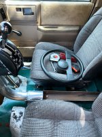
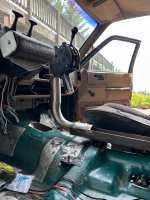
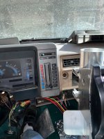
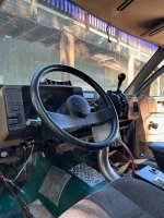
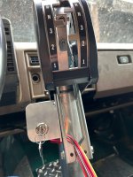
The column is locked in position with the wheel in a 9/3 position ...
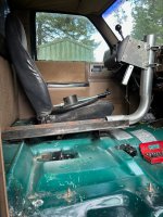
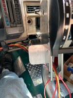
Great view of the instrument cluster

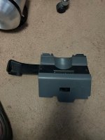
The new mount for the ignition switch is easily accessible as are all the other controls.

The tilt wheel adds a lot more access to things too......


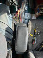
Overall the entire package is looking good.....I think that one of the nice dash carpets will be great.

The dash pad is better than many.....But a nice carpet will make it spiffy.......

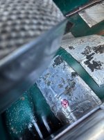
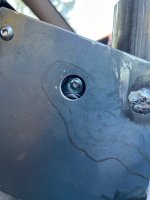
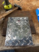
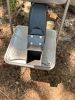
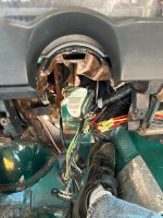
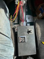
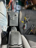
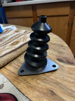
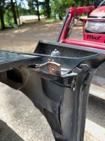
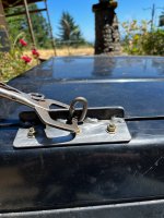
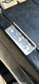
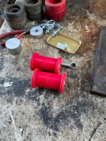
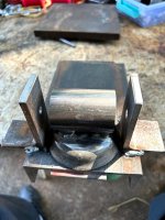
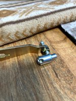
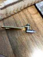
The strange convoluted gizmo IS NOT A SEX TOY
Its a GM Clutch shaft boot and retainer plate....Fits 1968-1972 Chevelle..The angle is perfect for whats needed....
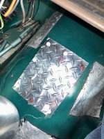
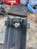
Fits perfectly on the floor WHERE THE RED DOT IS IN A PAST PICCY. Post 1563 ....The shifter cable slips through nicely and the boot will keep out noise....and other obnoxious stuff.....

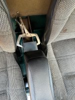
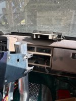
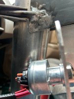
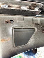
The loose wire on the lower left below the dash is the control wires for the wipers...The Blazer had a slightly different arrangement under the dash (Automatic tranny vs A stick in the single cab) and there does not seem to be the little hole in the support frame to stick the barb on the plug.....A zip tie to the rescue me thinks.

Also the ALDL Plug is hanging loose.....May attach it back onto the trim panel as it was from the factory......

Back in the day....TAHOE was a trim package......

Maybe this cat can become "Frankenhoe" :lmao:
 

Attachments

  • Column in1.jpg
    Column in1.jpg
    346.8 KB · Views: 50
  • Column in2.jpg
    Column in2.jpg
    567.3 KB · Views: 48
  • Column in3.jpg
    Column in3.jpg
    576.4 KB · Views: 46
  • Column in4.jpg
    Column in4.jpg
    560.2 KB · Views: 46
  • Column in5.jpg
    Column in5.jpg
    240.6 KB · Views: 47
  • Column in6.jpg
    Column in6.jpg
    447.5 KB · Views: 48
  • Column in7.jpg
    Column in7.jpg
    326 KB · Views: 46
  • Blood letting.jpg
    Blood letting.jpg
    386.1 KB · Views: 51
  • Shift cable boot.jpg
    Shift cable boot.jpg
    446.8 KB · Views: 50
Last edited:

Snowy Rivers

Well-known member
Yesterday turned into a mess.

I needed the little tractor to lift some stuff..
FLAT TIRE....This tuns into a many hour ordeal to get the tire fixed.

I drop the tire/wheel off at the shop...Come back in a while and my tire is sitting outside off the wheel .

I go look at it and the stick is still in the tire.....Fella comes over and explains that "They tried to fix it" but could not.

Right off my BS flag is at full staff.

OK.....Let's replace the tire....10 minutes later the dude comes out and tells me....That size is no longer available.....

I am not amused at this point.....and ready to turn into a real AZZ HOLE.

I asked with a little bit of civility....NOW WHAT???

Dude looks me in the eye...."Buy a new tractor"
Civility is off the table now.....
I looked him in the eye...."Get your skinny azz in that shop and fix this !@#$%^ tire"

He rolled the tire in the shop and about 15 minutes later rolls it back....This morning I discover the clown left the stick piece in the tire...Just patched it with a big truck tire patch......It will leak again when the stick wears through the patch....

This is what you get these days......I have zero patience with those who can't think on their feet.......Fixing a tractor tire is not rocket science......

So by the time we got home and got the tire back on the tractor....I was not interested in much....ARRRRRRGH
 

Snowy Rivers

Well-known member
Busy around here with things...

But did find some time to mess with the new ignition switch..
Worrying a half round hole in the switch bracket was fun...(Switch has a flat on one side where it goes through the panel to stabilize the switch)
Marked the round hole...then marked the flat needed.
Used a small end mill and and worried the bulk of the hole...cut the flat and then finished things by hand with a file...

Factory stuff is all punched.....But as the early summer rains came down this morning I got this little gem whacked out.

Bolted it back in....Still need to drill one hole in the shifter side bar to get the two bolt holes needed.

Some pics from various angles.....Plenty of clearance to connect the wires.....

I can reach through the lower opening in the steering wheel and access the key quite easily with my left hand....

I left some room at the top above the ignition switch in case we need a spot for another switch of some sort....
 

Attachments

  • Ignition1.jpg
    Ignition1.jpg
    374.7 KB · Views: 38
  • Ignition2.jpg
    Ignition2.jpg
    381.3 KB · Views: 40
  • Ignition3.jpg
    Ignition3.jpg
    398.3 KB · Views: 39
  • Ignition4.jpg
    Ignition4.jpg
    374.6 KB · Views: 35
  • Ignition5.jpg
    Ignition5.jpg
    482.6 KB · Views: 39
  • Ignition6.jpg
    Ignition6.jpg
    399.3 KB · Views: 36
  • Ignition7.jpg
    Ignition7.jpg
    375.4 KB · Views: 37

Snowy Rivers

Well-known member
Summer time and ranch domestics have been keeping me away from the project....but still getting some stuff going.
With the basic changes and additions made in the cab I have decided to get after the tilt front end....

Once the final body mods are made the last of the mechanical stuff can go ahead.

Pulled out all the containers of bolts, screws, nuts and washers and sorted out the best of both of the rigs used for the donor cabs.

Got that entire lot of stuff soaking in a pot of solvent (Regular gasoline) to clean off the oily crud and other debris.

Having a complete set of factory fasteners will allow things to go back together easily.....

Next comes power washing the fenders (Inner and outer) the hood and the core support.....
These are in good shape...albeit grungy........

I am not going to fight filthy parts......

Then comes getting the outer and inner fenders assembled back onto the cab along with the core support..

Some mock-up with lumber or ??? to rest the core support across the cat tub will be needed to get things where they need to be......

The radiator and brackets along with the fan shroud assembly (Split shroud ..2 pieces splits at center came from the Blazer)
Once the radiator mounting is in....The new "Nose cone/grille" can be fabricated and allow a place for the original core support to hinge from.......

Cutting the fenders to get a nice clean opening point for the forward tilt will take some imagineering.....
Simple enough....Just need to get the location right......

A couple urethane hood alignment pins from a big rig should be just the ticket to make getting things to close and line up right every time.......

Slow going.....And as usual....lots of thinking stuff through well......I do not want to mess up any of the parts.....
I do have 2 sets of front fenders.....BUTTTTTTTTTTTTTTTT...
 

Snowy Rivers

Well-known member
Finally got after getting the parts of the front clip cleaned up....The rig had a factory remote oil filter and it looks as though the previous owners just yanked the old filter off and let the oil drain into the fender and core support.

Helluva mess...Lots of high pressure water and degreaser....
The parts are finally cleaned.

Had to spend an hour fixing the washer...Stupid soap intake check valve broke off.....Soaked my azz really good.

Got the broken fitting out and screwed in a pipe plug.....


The current plan is to reassemble the front clip in its entirety and then sit it up on the cat......

Trying to manhandle the parts by the each will not be easy.

Thinking about adding a lift ring in the middle of the hood to allow the entire tilt front end to be lifted on/off easily.....

We will see how well that can be done.

Going to check out the hood to see what the underside looks like and where we can get a good way to fasten a lift rig on...
The hood will be fastened onto the fenders and the core support and basically be one piece......

The rear 18" give or take of the fenders will be fastened to the cowl and front of the cab.....Cut on an angle to allow the front end to tilt apart easily....

A piccy of the cleaned parts....One fender is not in the pic......also the hood is not there either.....

Tomorrows task to clean the hood....
 

Attachments

  • Frontclip1.jpg
    Frontclip1.jpg
    796 KB · Views: 39

Snowy Rivers

Well-known member
Good fortune smiled yesterday and the front clip came back together with reasonable ease.

There were a few of the Uclip nuts where the core support bolts on that were just in too bad of shape to reuse them...
With a few scrounged from the extra fenders left from the Original Clip off the cab (Green/White single on the cat) we had enough to gitterdone

The original fenders had enough damage that they were just not good candidates (Big dings and a dent or two or more)

With the clip together comes the task of IMAGINEERING a way to (1) fasten the hood to the fenders AND in a spot that lends itself to tilting forward easily.

Spent a couple hours sitting under the hood with my doodle pad and pencil and the Imagineering lamp turned on.

The plan as always with this project is to use as much original parts, pieces and such from the factory stuff that is left after disassembly...

A big box of metric bolts and such just needing a job.....

Fastening the hood to the fenders and have lifting points at 3 places was right up there on the list of importance.

The original hinge mounting on the underside of the hood just jumped out LOOK AT ME

The stepped area where the hood sits flush with the fenders has enough room to get a nice sheet metal bracket slipped in....Bolt to the hood using the original bolts and be able to bolt into the fenders.

The original latch assembly up front is perfect to secure the hood there....

The rear brackets have another plus....They can be allowed to stick above the hood a few inches and have a round hole to serve as a lift point.....

That gets two lift point dealt with.....
The third lift point will be a nice handle to tilt hood assemble forward......(Most big rigs have a grab handle of some sort at the center front of the hood to tilt it open.....


I have not found anything readily available YET that will fit the area available under the front of the hood....

With the under hood pad removed (Junk) The are several round and oblong holes in the stiffener pieces of the hood that allow access to drill through the hoods top sheet.

A pair of angle brackets and a round bar between them should be quite satisfactory.

This will come together easily .....
My main concern WAS/IS getting the hood anchored to the fenders and making the angled cut to allow the tilt portion to lift away from the short section of the fenders left that bolt to the lower cowl area of the cab.

One piccy shows a hastily chalked line ABOUT where the fenders will get cut.

The remaining section of the fenders bolt to the top of the cowl in two places......Two places just ahead of the front of the door and one near the bottom pinch weld area just ahead of the door.....

Luckily the lower bolts and nut inserts were in great shape on the black fenders.The parts on the original fenders of the cab were badly rusted and broke off even after repeated soaking with Skunk pizz.

We have plenty of the proper bolts and hardware to get all this together.

The air vent panel that fits at the base of the windshield uses one of the top fender bolts to secure it on each side.

This panel has a GUTTER of sorts to channel water out to the edges where it drains down a passage at each side of the cowl..


Earlier I had scrounged up some rubber seal from a different rig that fit over the area of the air vent panel that the hoods rear flange sits on ....Hopefully this will help even more at keeping water from dripping down onto the distributor.......

After sitting under the hood it became quite obvious that the inner fenders will not be needed.....An easily removed flat panel can be fitted along the tapered front portion of the Cat tub on each side that extends up to near the S-Wagon hood to keep snow and debris out of the engine bay....

The opening in the core support where the original cooling stack was mounted is large ....I am thinking that this will need to be closed up to help keep snow out of the engine bay......We can deal with this at a later time....No real interference with other parts.

The Core support has two reinforced spots where the original rubber mounts were ......Looks like a perfect place to build our tilt mounts.....

I may use various original items to accomplish the mounting.

A factory rubber mount and a "T" bolt with a steel tube welded to it that will carry the Urethane bushings.

The area of the core support was designed to carry the clip and be subjected to some twisting moment of the frame.

Looks like a great place to pretty much use as it is.....A little modification....Good to go....


I spotted some stainless steel sheet metal at the steel yard......NO RUST....... Good for the rear brackets on the hood to secure it and the lift points.....

Several piccy's

Paint on the fenders leads me to believe these may be replacement fenders......Primer on the inside and not black paint.

The factory paints everything in and out to the original color.........Both fenders are not painted on the inside......Hood is painted in and out......The rig may have seen damage.....

The story goes that this rig was a Dingy behind a large Coach owned by an older couple......No other info...

No matter.....It is what it is...USABLE PARTS.....

The questions came up when I found a misalignment in the RH fender that GM would not have let go.....

Then the paint issue....Aftermarket fenders ?????? Maybe

Little red tractor is sure handy for packing stuff around..

The hood was across the yard and I was not interested in carrying it....
 

Attachments

  • Frontclip11.jpg
    Frontclip11.jpg
    330.9 KB · Views: 30
  • Frontclip10.jpg
    Frontclip10.jpg
    337 KB · Views: 32
  • Frontclip9.jpg
    Frontclip9.jpg
    284.9 KB · Views: 32
  • Frontclip8.jpg
    Frontclip8.jpg
    453.6 KB · Views: 32
  • Frontclip7.jpg
    Frontclip7.jpg
    338 KB · Views: 30
  • Frontclip6.jpg
    Frontclip6.jpg
    354 KB · Views: 32
  • Frontclip5.jpg
    Frontclip5.jpg
    496.4 KB · Views: 35
  • Frontclip4.jpg
    Frontclip4.jpg
    659.2 KB · Views: 32
  • Frontclip3.jpg
    Frontclip3.jpg
    730.5 KB · Views: 34
  • Frontclip2.jpg
    Frontclip2.jpg
    667.4 KB · Views: 32
  • Frontclip1.jpg
    Frontclip1.jpg
    745.5 KB · Views: 32
Last edited:

Snowy Rivers

Well-known member
Got some forward motion on the brackets to fasten the hood to the fenders....

Snooping through the short stock rack....Found some material that we used on the rear cabin mountings.

1/4" x 2-1/2 x 2-1/2 Formed angle....I cut a test piece to see if it would fit in the gap between the fenders and the hood.

BINGO.....A perfect fit.

Cut the original hinges off and used the mounting pad portion (Holes/slots already there....Perfect.

Set things up and tack welded all the parts together in place to get a good fit.

Wind was calm this morning early....Was able to use the mig welder and get decent welds....
TOOK THE PICS A BIT AGO.....Wind is blowing now.....

Got a foot of bare steel chain and will cut out 2 links and weld one on each of the flanges that stick up between the hood and the fender....Great place to grab onto the assembly with the lift rig and the skid steer.....

The component fit is pretty good....As good as it was with the rubber spacers that are in the area to locate the hood...

I need to drill three 5/16" holes in the part that hangs over the top of the fender.
Will get that done tomorrow and then get the chain links welded on.....Then paint the parts.

Next comes the lift/tilt handle up front .....Need to do some more sitting under the assembly and see what we can do.....

Maybe a larger aluminum Angle and mill a HAND SLOT in it......We shall see...........The hood is not flat....Will need to scope that out...

My little "Cat Engineer" she is always a big help....(11 yo Sphynx)
 

Attachments

  • Hood to fender brackets1.jpg
    Hood to fender brackets1.jpg
    461 KB · Views: 37
  • Hood to fender bracket6.jpg
    Hood to fender bracket6.jpg
    426.4 KB · Views: 32
  • Hood to fender bracket5.jpg
    Hood to fender bracket5.jpg
    600.4 KB · Views: 36
  • Hood to fender bracket4.jpg
    Hood to fender bracket4.jpg
    474.2 KB · Views: 35
  • Hood to fender bracket3.jpg
    Hood to fender bracket3.jpg
    586.1 KB · Views: 37
  • Hood to fender bracket2.jpg
    Hood to fender bracket2.jpg
    441.8 KB · Views: 35
  • IMG_6329.jpg
    IMG_6329.jpg
    468.3 KB · Views: 34

Snowy Rivers

Well-known member
Unexpected domestics got in the way of my work on the cat yesterday......But did get the brackets and the top of the fenders drilled...

Decided to use a piece of 3/8" x 1" aluminum bar inside the fender as a "Nut plate" to fasten the brackets to......

Getting individual nuts and washers up inside the fenders is a tad sketchy (Just a tight spot to get into)
The bar can easily slide into the location and pulled up snug with a wire in the center threaded hole (Three holes in the bracket and nut plate)

May install the bolts on the end two holes from the bottom (Lock tight them) and install the center bolt from the top down and use the aluminum thread only ......


Getting a secure anchor in this area does not give a lot of options as far as mounting points.

The two tilt front end rigs I was involved with in the past saw the assemblies (Hood and fenders) welded together...

I want these parts to be replaceable EASILY if need be.....The hood on this setup will be nearly stock EXCEPT for the tilt handle / lift point up front........


I hope we do not need to replace any parts...But Chit happens ya know ......

The Right side fender slides in real close around the heater box at the cowl.....This makes options for fastening points very limited between the hood and the fender......Hence the choice to use the original hinge and it's mounting point.....

Will have piccys soon...
 

Snowy Rivers

Well-known member
Things are coming together really well

Got the "Nut plates" that go up inside the fenders drilled and tapped.

The big issue was gonna be getting them inside the fender....The area is tight.....and hands do not fit.
Decided to screw the two end bolts in from the bottom (Will loctite before final assembly) and leave the center hole open.

Then slide a wire down through the bracket...through the nut plate and make a loop....Pull the plate up and the bolts through the fender, the bracket and then add the washers and nuts (Nylocks will go on at final assembly)

Absolutely love it when a plan comes together........

Pics show things well
Bottom up shots show the original hinge, bolts and the new angle material.

Getting the nut plate up and into place was sweeeeeeet....Just like Gigging Frogs

One shot shows the front of the hood....Handle will bolt through up here.....Still need to finalize the handle design....

The chain links get welded onto the bracket (Rear lift on each side)


The assembly is very sturdy feeling now that things are all tight... Should work well..
 

Attachments

  • Hood to fender bracket22.jpg
    Hood to fender bracket22.jpg
    379.7 KB · Views: 37
  • Hood to fender bracket21.jpg
    Hood to fender bracket21.jpg
    501.7 KB · Views: 33
  • Hood to fender bracket20.jpg
    Hood to fender bracket20.jpg
    474.2 KB · Views: 35
  • Hood to fender bracket19.jpg
    Hood to fender bracket19.jpg
    560 KB · Views: 32
  • Hood to fender bracket18.jpg
    Hood to fender bracket18.jpg
    471.9 KB · Views: 34
  • Hood to fender bracket17.jpg
    Hood to fender bracket17.jpg
    471.9 KB · Views: 31
  • Hood to fender bracket16.jpg
    Hood to fender bracket16.jpg
    420.5 KB · Views: 32
  • Hood to fender bracket15.jpg
    Hood to fender bracket15.jpg
    400.4 KB · Views: 33
  • Hood to fender bracket14.jpg
    Hood to fender bracket14.jpg
    546.4 KB · Views: 34
  • Hood to fender bracket13.jpg
    Hood to fender bracket13.jpg
    478.6 KB · Views: 36
  • Hood to fender bracket11.jpg
    Hood to fender bracket11.jpg
    454.6 KB · Views: 33
  • Hood to fender bracket10.jpg
    Hood to fender bracket10.jpg
    646.4 KB · Views: 34
  • Hood to fender bracket9.jpg
    Hood to fender bracket9.jpg
    544.7 KB · Views: 34
  • Hood to fender bracket8.jpg
    Hood to fender bracket8.jpg
    442.3 KB · Views: 37
  • Hood to fender bracket7.jpg
    Hood to fender bracket7.jpg
    385.5 KB · Views: 32

Snowy Rivers

Well-known member
Wrapped up the rear brackets....Welded on the lift eye and got things painted.

Reassembled things.....

Looking at the front area (Pix) I need to get the materials to make the front tilt/lift handle

Not sure if anything will be open Monday......Definitely not Tuesday...

The plan is a couple pieces of aluminum angle with a 1-1/4" round aluminum bar between them....Bolted to the front of the hood about 2 inches back from the front flange........

Does not need to be super herky.....To tilt the clip will not take a lot of ooooomph......


Will post when I get materials and have something to look at....
 

Attachments

  • Hood to fender brackets24.jpg
    Hood to fender brackets24.jpg
    654.1 KB · Views: 31
  • Hood to fender brackets23.jpg
    Hood to fender brackets23.jpg
    557.7 KB · Views: 29
  • Hood to fender bracket25.jpg
    Hood to fender bracket25.jpg
    613.1 KB · Views: 30

Snowy Rivers

Well-known member
The Holiday shot me in the foot.
Steel yards are closed until the 5th.....I wanted to get some aluminum angle for the front tilt handle on the tilt hood....

Just gonna have to wait.....

Arrrrrrgh...l
 

Snowy Rivers

Well-known member
Front "Gun Sight" finished.....Sweeeeeeeeeeeeeet

Yesss...The front handle to tilt the hood assembly is pretty well done....

Getting at the two most forward nuts is a bit of an issue...So I ordered some Nuts with free floating washer..

This will make installing the front two nuts on each part of the brackets much easier...

Decided to use these on all 12 locations.......

Sooooo....

The front clip is now ready to sit up on the cat for a test fitting .....Soon.....

The clip gets bolted to the cab as it was for it's life as an S10 PICKUP/Blazer.

Some blocking will likely get tossed in across the top of the 2100 tub to position the assembly correctly...

Then comes the fun part.....The radiator and it's mountings......The front nose and the last of the goodies to allow the hood assembly to tilt....

Working on the design of the pivots for the tilt assembly.....Got the idea sketched out....Just need to get the clip in place to be sure the idea is a sound one..
 

Attachments

  • Front handle5.jpg
    Front handle5.jpg
    227.1 KB · Views: 31
  • Front handle4.jpg
    Front handle4.jpg
    601.7 KB · Views: 32
  • Front handle3.jpg
    Front handle3.jpg
    692.5 KB · Views: 33
  • Front handle2.jpg
    Front handle2.jpg
    476.1 KB · Views: 35
  • Front handle1.jpg
    Front handle1.jpg
    506 KB · Views: 35

Snowy Rivers

Well-known member
Got after the "Pivot" for the Tilt Hood assembly today.....

The original mounts for the core support were perfect to build the tilt assembly.

Just had to turn them around backwards and inside out....Welded in a bolt and welded on a tube to hold the urethane bushings.

Needed an adapter to fit inside the upright in the core support and align the tilt assembly..... (One machined...need one more )

Big issue was building a jig to keep all the parts straight while they were welded....
The side pieces line up the tube.....Used a wood dowel that fit the tube and ran a bolt through it.....
The dowel got a tad smokey after welding.....BUT IT MADE IT....

GOT THE PARTS DONE....AND PAINTED.....No piccy of them with paint.....

Were able to come up with enough materials to do it all.....Right from stock....

The red bushings were spring bushings left from another job years ago.....They needed a job.....

With the body starting to get close I am thinking about the drive train.

Engine and tranny.....

Decided to see if another TH 350 could be scared up reasonable to rebuild and not need to disassemble things this summer.

I really don't want the cat scattered all over......

The 305 and TH 350 that are in the cat can sit there until the fresh 406 and a gear box are done.....Then yank the cat apart and swap things.

I found a 350 box this afternoon and will go see tomorrow......

Supposed to be in running order.....Going to go through it totally anyway.......

350 boxes are getting tougher to scare up these day.....Having a spare is a good idea me thinks.

Gonna go full manual valve body.....Whatever hole its in is what you get.....Set it up as a select shift......

Far better than all the busy box game.....Getting these to shift in auto mode with the super low gears in the diffy is a joke.....

BOOM BOOM BOOM....HIGH GEAR
 

Attachments

  • Tilt assembly6.jpg
    Tilt assembly6.jpg
    591.4 KB · Views: 27
  • Tilt assembly5.jpg
    Tilt assembly5.jpg
    478 KB · Views: 29
  • Tilt assembly4.jpg
    Tilt assembly4.jpg
    232.7 KB · Views: 30
  • Tilt assembly3.jpg
    Tilt assembly3.jpg
    383.4 KB · Views: 31
  • Tilt assembly2.jpg
    Tilt assembly2.jpg
    487.9 KB · Views: 31
  • Tilt assembly1.jpg
    Tilt assembly1.jpg
    507.2 KB · Views: 30

Snowy Rivers

Well-known member
Went and took a peek at the TH350 box I spoke of...
The story goes like this.....

The tranny was in a 1932 Roadster with a 350 in front of it.....The owner wanted a different box (Likely a 4 speed OD box)
And he wanted more power.....

So the story goes....The fella I got the box from ...."Was given the engine and tranny from the roadster for helping the owner swap the power train"

Sounds plausible ......

Box is very clean.....Oil is RED ...NO STINKY BURNT DOG POOP SMELL....
Just way too clean to have many miles on it..

Guy tossed in a cast aluminum oil pan too.

Rotated the shafts ...no odd noises....

Won't really know much until the beast in on my bench and apart.....

But it was worth $125 based on the visual......

No converter....I want a converter with standard stall and brazed blades in the turbine and pump sections.

When it comes to auto tranny's I want to have my fingers inside it....Waaaay too many stories out there about how stuff was built and all that noise......

Gonna see if I can scare up any numbers off the case that identify it.

This may have been a GM over the counter unit.....

The surface where the trans meets the engine block is clean and no signs of the usual burnishing the occurs on the aluminum case from the tiny little bit of movement between the engine and trans......

The inside of the bell housing is really bright ....Even rebuilt boxes will have some stains and oxidation from the years in service

Back when I did tranny work we cleaned things good.....But even the cleaning products we used did not bring the alloy THIS CLEAN.

Maybe the story of this box is legitimate .....

Factory fitted boxes are usually not painted.....Hot rod stuff ....Many times


I am indeed curious as to wasssssup in this little jewel.....

Couple pix
 

Attachments

  • TH350 Beaverton1.jpg
    TH350 Beaverton1.jpg
    600.1 KB · Views: 32
  • T350 Beaverton2.jpg
    T350 Beaverton2.jpg
    467.4 KB · Views: 29

Snowy Rivers

Well-known member
Took some time this morning and lifted the little tranny up flat with the tractor and straps. Dropped the pan straight down....

The dip stick hole was open.....I did not want to have anything that may have dropped into the pan to fall down into the gear train.

Pan had clean oil in it....But a lot of rust stain in the pan.....Worrisome.......But the valve body and other parts did not show any signs of water having been in the unit....

Brass filter screen.....No sludge or signs of any clutch materials or other crap in the unit...

Needs to come apart totally and snooped through....

I want a 5 clutch high drum......and a few other mods in this box.

The bolt holes in the pan rail were in need of cleaning with a tap....One hole needed a Helicoil Will loctite in a long Allen head set screw in two holes to provide a mounting point for the shift cable bracket.

The aluminum pan fits nice....Had to get Stainless steel Allen socket screws for the pan....Stock bolts do not fit

Still thinking this was a good buy....
 

Attachments

  • T350 Beaverton3.jpg
    T350 Beaverton3.jpg
    644.8 KB · Views: 26

Snowy Rivers

Well-known member
Decided to get the shifter cable out and stuff it down through the floor and see how it looks in relation to the tranny.

The standard cable with most Winters shifters is the 5 foot....

Well...As I had thought....The 5 foot was too short......By about 2 feet......

Called Winters.....The longer cables are on back order.....ARRRRRRGH

Called a local heavy truck supply house up in Portland.....They had the HD version of the 1/4-28 cable....

(These have the groove style mounting as well as the double nut on a threaded sleeve just aft of the groove )

The 7 footer fits in well.....

The mounting at the tranny is a bit sketchy.....The steel bracket is OK...But the stamped steel clamp that goes into the groove of the cable is a POS.....

The connector that snaps onto the little ball on the shift shaft arm is a !@#$% JOKE.

Waaaaaaaay too small and the snap on end has a spring and a little groove to retain the cable.......
Going to machine up a custom Clevis and use a 1/4" grade 8 bolt through the shifter shaft arm......
Much stronger and no chance of things coming apart.....

All these parts are mission critical and are not readily accessible without removing the cab....
( Power pack goes in..... the cable hooks up to the trans.....Cable threads up through the floor as the cab goes on.....)

The bracket that bolts to the tranny is OK....Going to bolt a piece of angle to the 4 holes in the bracket and add a hole that the cable can fasten too using the nuts that go on the threaded sleeve of the cable.

These mods will get this assembly up to par.....IF..... the parts were accessible easily I might not be so anal about these things
 

Attachments

  • Shifter linkage at trans6.jpg
    Shifter linkage at trans6.jpg
    472.9 KB · Views: 27
  • Shifter linkage at trans5.jpg
    Shifter linkage at trans5.jpg
    466.1 KB · Views: 29
  • Shifter linkage at trans4.jpg
    Shifter linkage at trans4.jpg
    486.3 KB · Views: 25
  • Shifter linkage at trans3.jpg
    Shifter linkage at trans3.jpg
    390.2 KB · Views: 27
  • Shifter linkage at trans2.jpg
    Shifter linkage at trans2.jpg
    332.8 KB · Views: 25
  • Shifter linkage at trans1.jpg
    Shifter linkage at trans1.jpg
    371.8 KB · Views: 25

Snowy Rivers

Well-known member
Still fooling with the shifter parts.......

This set up needs to be absolutely spot on.....I went to the steel yard yesterday to get some materials to make some of the parts I want to replace......

Came away less than happy....Wanted a piece of 5/8" aluminum round to machine up a clevis for the tranny end of the cable.....No luck....Had to order a foot of the stuff online....

$9 and free shipping.....Cost more in fuel to drive to the big city to get the stuff....I can wait a few days....

The plan is to get the shifter out of the cab and then clamp it up on the tractor bucket at about the same height above the tranny as it will be in the cat.....The adjustments can all be set and stuff locked in place.......

This will save a bunch of fooling around later when the fresh tranny goes into the cat....

If any issues arise they can be dealt with readily.....

The HD cable is a tad different than what Winters sells.....BUT...The one we have is locally available off the shelf .....If down the road it needs replacing.....Easy to get one that is identical........


I am seriously thinking about making an access port in the side of the tub on the cat that will allow getting at the shifter cable mounting on the tranny....

It is in a tough place to deal with......
The front axle air suspension and arm and the rear tranny mount are all clustered in close proximity......

This may not be possible......Serious study of the area is needed.....

If it's possible I do not want the track to need to be broke apart to get into things.....

Thiokol had it right with the tilt cab.....sadly tilting the cab is not an option....Way too heavy......Access if possible needs to be easy and with only tools that one might have in the field....


Ahhh yessss...The joys of a Roll yer own build....
 

Snowy Rivers

Well-known member
Finished up the shifter cable bracket assembly today.....

Used the bracket that came with the shifter....Turns out the bracket is a heat treated piece....Very hard material....Wanted to dril the bolt holes out to 1/4"....Squuuuuuuuuueeeeeeeeeeeeeek said the drill.

So....Using the 10-32 Allen bolts.....

Machined two aluminum pieces to hold the cable and bolt to the bracket.....
The front piece has a 1/2 inch hole that the grooved portion of the cable slips into.....A set screw hole front and back with a round bottom 1/4" set screw fits into the groove to secure the cable.

The inner set screw fits flush with the mounting bracket and once the blocks are bolted onto the bracket the screw can't loosen up.....The outer set screw has a jam nut and it adds support to the cable.

The rear block slips onto the threaded portion of the cable and bolts to the rear most holes in the bracket.

A set screw with jam nut adds a bit more security to the cable to stop any wiggle.....

The cable actuates the tranny range arm perfectly.

Tomorrow we can clamp the shifter to the tractor bucket and hook it up....Adjust things and see how it all works.

I want a bit stouter quick connect on the tranny end of the cable...

The one with the kit is a bit sketchy......

So far....Very good setup.....

The rubber wiper seal on the cable ended up a tad too tight against the block....Had to spot face the end of the block to make a bit more room.....It was gonna be close....Just ended up a bit closer than it looked like it would be...
 

Attachments

  • Cable bracket at trans10.jpg
    Cable bracket at trans10.jpg
    422.9 KB · Views: 31
  • Cable bracket at trans9.jpg
    Cable bracket at trans9.jpg
    344.9 KB · Views: 28
  • Cable bracket at trans8.jpg
    Cable bracket at trans8.jpg
    507.1 KB · Views: 29
  • Cable bracket at trans7.jpg
    Cable bracket at trans7.jpg
    435.8 KB · Views: 29
  • Cable bracket at trans6.jpg
    Cable bracket at trans6.jpg
    439.9 KB · Views: 27
  • Cable bracket at trans5.jpg
    Cable bracket at trans5.jpg
    627.1 KB · Views: 30
  • Cable bracket at trans4.jpg
    Cable bracket at trans4.jpg
    306.3 KB · Views: 27
  • Cable bracket at trans3.jpg
    Cable bracket at trans3.jpg
    358.2 KB · Views: 29
  • Cable bracket at trans2.jpg
    Cable bracket at trans2.jpg
    273.7 KB · Views: 27
  • Cable bracket at trans1.jpg
    Cable bracket at trans1.jpg
    486.3 KB · Views: 28
Top