
-
Please be sure to read the rules and adhere to them. Some banned members have complained that they are not spammers. But they spammed us. Some even tried to redirect our members to other forums. Duh. Be smart. Read the rules and adhere to them and we will all get along just fine. Cheers. :beer: Link to the rules: https://www.forumsforums.com/threads/forum-rules-info.2974/
You are using an out of date browser. It may not display this or other websites correctly.
You should upgrade or use an alternative browser.
You should upgrade or use an alternative browser.
Astro van cat conversion
- Thread starter Snowy Rivers
- Start date
Snowy Rivers
Well-known member
Nope.....not at all.
Winter found us with snow and cold weather......
Not even going to venture outside for anything other than feeding the horses and going to get groceries.....
Mid Feb somebody gave us the damned virus.....Been beating that stuff off....
Have not felt like doing much of anything........We have not had a big snowfall, about a foot at the worst of it.....
Cycling between snowing, melting, snowing.....temps down in the teens ....more warming, more snow....REPEAT....
With March here the nasty weather SHOULD NOT last long......Butttttttttttttttttttttttttttt.....I have seen 6"-8" snow dumped at times in March..
Last year we had a 6" dump in early April.....One day wonder.....Just enough to make a mess and knock out the power for most of a day......Heavy wet snow ya know.......
The only thing somewhat exciting (Subjective)
We found ourselves in need of a rig that can haul more than 4 to 5 people.
The Avalanche pickup we had was not cutting it.
Sold it on Craigs list and then had to find a different rig....Needed to be 4x4 and have a buttload of seats.
Good used rigs are a PITA to find.....LOTS OF JUNK OUT THERE...
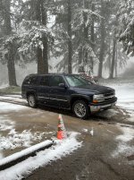
Finally scored a 2005 Suburban ......Local. rig....NO SALT
Decent shape and the price was right.....
I am not a fan of those 20" "Pimp wheels"
Pics were taken just before we got the foot of snow ......Rig did it's job well
So this is about the extent of things for now
As far as the cat project goes.....It is sitting in it's place waiting for good weather to come......
I have wanted to get to the machine shop and get the Cyl heads.....They have a couple feet of snow there and I am not gonna go fight getting in and out of the steep driveway......
Winter found us with snow and cold weather......
Not even going to venture outside for anything other than feeding the horses and going to get groceries.....
Mid Feb somebody gave us the damned virus.....Been beating that stuff off....
Have not felt like doing much of anything........We have not had a big snowfall, about a foot at the worst of it.....
Cycling between snowing, melting, snowing.....temps down in the teens ....more warming, more snow....REPEAT....
With March here the nasty weather SHOULD NOT last long......Butttttttttttttttttttttttttttt.....I have seen 6"-8" snow dumped at times in March..
Last year we had a 6" dump in early April.....One day wonder.....Just enough to make a mess and knock out the power for most of a day......Heavy wet snow ya know.......
The only thing somewhat exciting (Subjective)
We found ourselves in need of a rig that can haul more than 4 to 5 people.
The Avalanche pickup we had was not cutting it.
Sold it on Craigs list and then had to find a different rig....Needed to be 4x4 and have a buttload of seats.
Good used rigs are a PITA to find.....LOTS OF JUNK OUT THERE...
Finally scored a 2005 Suburban ......Local. rig....NO SALT
Decent shape and the price was right.....
I am not a fan of those 20" "Pimp wheels"
Pics were taken just before we got the foot of snow ......Rig did it's job well
So this is about the extent of things for now
As far as the cat project goes.....It is sitting in it's place waiting for good weather to come......
I have wanted to get to the machine shop and get the Cyl heads.....They have a couple feet of snow there and I am not gonna go fight getting in and out of the steep driveway......
Attachments

Snowy Rivers
Well-known member
Thanks for the best wishes
NOT POSITIVE ON THE CRUD.....Seemed like a nasty cold....But it is hanging on for a looooooooooooooooong time.
A cough that will not quit.....
But it is slowly getting better.....
I know for sure we had the Rona twice....
The last time was Jan 22......
We had some crap in December just before Christmas.....and then this last go round mid Feb
There is so much junk going around.......New Rona variants seem to be popping up every few weeks.....
A damned nuisance ....
How much snow ya got ????
Snowy Rivers
Well-known member
That is serious snow depth
Snowy Rivers
Well-known member
Weather is warming up- SOME
Some 55-60F on the horizon....
Starting to think about work on the cat again....
I have jumped back and forth from using air for the steering to using hydraulics and back and forth..
I finally got some top notch information on hydraulic valves and other goodies to make it happen using off the shelf components.....
The stock GM steering pump can provide 1200-1500 PSI and about 4 GPM of oil.
The issues has always been the control valves.....The original valves used by Thiokol are no longer available.
These valves had an adjustable pressure setting to get to the nominal 400 psi delivered to the cylinders on the OC-12
The Original cylinders are usable and all the original linkage and such are intact....
The 2100 used direct pressure off the main hydraulic system....routed through a priority valve at 2 GPM to the controls....
Getting the pressure where I wanted it was constantly a stone to trip over........
I discovered a company called "Brand Hydraulics" They offer a Priority flow divider that will also allow managing the pressure .....400 psi is an easy point to reach......Most of the valves of this type talk about adjustments in the 1000-5000 psi range......Below 1000 psi and the availability goes away.....
Brand Hydraulics offers a part # FG52 that allows 2 GPM priority flow (Factory Thiokol spec)
The pressure specs can be special ordered to the 400 we need.
Next came the control valves.....Continental offers a nice 03 size 4/2 way mono-stable (Spring return) 12 volt actuated
4 port.....2 position with field serviceable solenoid coils......
One valve for each side (Steering band/cylinder) The stock factory GM steering column/wheel can be retained and a simple set of micro switches actuated by an arm on the steering shaft.....
A simple centered spring assembly to offer some resistance to the steering wheel. Turn the wheel left or right to the stop to actuate the steering control valve......Bands are either on or off...../Same as Thiokol did it on the 2100.
The Big machines require a positive action on the bands to keep from wearing out the bands too quickly.
The continental valves are well within the budget......The flow priority flow divider too is budget friendly
Hose for the system can be "Field Serviceable" Parker type with reusable fittings (No crimping required)
I originally wanted mechanical valves and not electric.....Available...YES.....Special order only $$$$$$$$$$$$$$$$$$$$$$$$$$$$$$$$$$$$$$$$$$$$$$$$$$$$$$$$$$$$$ And a minimum quantity too......Very spendy.....The continental valves are an off the shelf item.......
I know this part of the cat has been beat on multiple times and I have looked at hydraulic and air.....
Air has only one caveat....(Actually more) but the available compressors that will fit in the cat are very limited and all the options are less than perfect as far as rated duty cycle.
The STEERING PUMP option is designed for mega miles of trouble free operation......
The factory setup on the 400 engine is perfect and the 1998 L31 engine serpentine drive is a sweet fit in the cat.....
I think that we will still modify the AC compressor to pump air and add one air tank to the cat so we can have the air horns and have onboard air for ???????????????? tires and whatever.
This plan finally makes good sense....both $$$$ wise and function wise.....
The hydraulic valves are a decent price at $163.00 each.....The custom mechanical valves were NORTH OF A GRAND EACH.......
With the components finally sorted out......Just need to draw up the schematic....figure out the hose routing....Where to mount the valves and such.
I found another single cab in really decent shape the other day.....My front cab is not great....Windshield cracked bad.....plus the wiring is real flakey.
The current cab served well to get the mountings all located....Be sweet to have a complete cab that is in great shape....
The one i found has a good windshield, slider rear window.......Dash is pristine, tilt steering wheel......Just sit it on and bolt things back up.....
The front clip off the S Wagon will all bolt on and do the tilt thing....
Just an upgrade to better parts.....
Summer is coming..
Snowy Rivers
Well-known member
Doing the PAPER ENGINEERING on the hydraulic system for the cat steering.
Spent a good amount of time researching info on the GM Saginaw P series steering pumps.
There is a trainload of BULL SNORT info floating about.
Finally got hold of a company in Texas that does custom off road steering for Rock crawlers and other dirt rigs.
These guys had the ANSWERS I WAS LOOKING FOR.
Each power steering pump is designed and set to provide the volume and pressure needed for the application.
GM P series pumps have been around for decades....They can provide up to 1400 PSI and 4 GPM
For the cat we need the 4 GPM to be able to provide 2 GPM to the steering (Factory Thiokol 2100 spec)
Plus we need to be able to split the flow and send the rest of the flow back to the tank through the cooler.
The cat requires 400 PSI at the OC-12 cylinders......
The key to getting this pressure is a kit from BORGESON that provides shims to adjust the pressure control valve
(Mustang 2 rack and pinion require about 700/800 psi ) Just a reference.
There are valves sold for this application.....Adding a couple more shims to the adjuster nut assembly will get us to 500 psi easily.
Adding a HEIDTS pressure control (PS 102) with a gauge will allow FINE TUNING things into the sweet spot of 400 psi at the OC-12.....(This also allows an additional safety in the system to protect the diffy)
A 1-1/2 gallon aluminum oil tank can provide the much needed extra oil capacity.
The Oil flow is accomplished with an SP27 flow control that threads into the pump in place of the stock fitting....
Now that we have the pressure and volume.....WE need to put it to work.
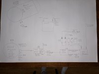
Oil flows from the pump to the PS102 (HAS A GAUGE ON IT) then to a priority flow divider (Thiokol used this in the original system) 2 GPM to the steering system....and the remaining oil flows to the tank through the cooler.....
The priority flow heads to a 50/50 flow divider to split the flow equally to both control valves.....
The valves are a 4/2 way solenoid valve 12 volt operated
The VS6M VALVES ARE ACTUATED BY A HEAVY MICRO SWITCH mount to a bracket and the original steering wheel/column provides the user interface.....SIMPLE and effective....
A spring loaded centering device keeps the steering wheel centered when not turning......
When the steering is not active the oil flows from the tank port to the A port and back to tank
When steering is called for the oil flows to the B port to the OC-12 Band cyl at 400 psi.
When the steering is released the valve switches off and the oil from the cylinder is exhausted from the B port to the Tank port and back to the tank...(Yesss....2 tank ports so the system can always sit idle when not needed and flow fluid freely.....
The excess flow from the priority valve should be able to keep a decent amount of oil flowing through the cooler to the tank so the system will stay at a safe temperature.......
This arrangement uses pretty much readily available off the shelf parts that can work well and last a long time.....
The first draft of the hydraulics in not really pretty.....But has all the goodies in place.
Looking at the cat this morning and I do believe that a bolt on bracket slightly above the engine and between the inner fenders of the S wagon tilt front clip will allow a great place to mount the Tank and all the valving and hoses in a neat spot.
A pair of #8 hoses run to the rear of the cat to a manifold and then the smaller hoses connect to the Diffy cylinders.
The #8 hoses will help to keep response time up both oil in and out...
Having all the goodies located in one place should cut down on the amount of hose needed....
Air flow in through the original grille will keep the hydraulic equipment fairly cool....
The engine radiator is down below in the original location in the tub....
Mounting things this way should make access to such things as the distributor, carburetor and the serpentine belt system fairly easy......
FINALLY after only a couple years of screwing with different ideas.....This looks good....The cost is reasonable too.....
I am sure the final realization will morph a little bit....But at present it looks good.
WE need to get the radiator and the tub nose assembly in place before firming up the final location of the Hydraulics mounting.......
I did not get the original front nose of the cat.....will need to fabricate that and get the radiator mounting and shroud dealt with.
The new "Nose cone" needs to be stout enough to mount the tilt front end on too......
But overall there appears to be plenty of room in the engine area to get all the goodies in place.
Oil cooler can go in front of the radiator.........
A sturdy grill sheet in front of the radiator in the Nose cone will be needed...
The 2100 is not all that far off the ground......Some perforated 14 gauge should be good........
Spent a good amount of time researching info on the GM Saginaw P series steering pumps.
There is a trainload of BULL SNORT info floating about.
Finally got hold of a company in Texas that does custom off road steering for Rock crawlers and other dirt rigs.
These guys had the ANSWERS I WAS LOOKING FOR.
Each power steering pump is designed and set to provide the volume and pressure needed for the application.
GM P series pumps have been around for decades....They can provide up to 1400 PSI and 4 GPM
For the cat we need the 4 GPM to be able to provide 2 GPM to the steering (Factory Thiokol 2100 spec)
Plus we need to be able to split the flow and send the rest of the flow back to the tank through the cooler.
The cat requires 400 PSI at the OC-12 cylinders......
The key to getting this pressure is a kit from BORGESON that provides shims to adjust the pressure control valve
(Mustang 2 rack and pinion require about 700/800 psi ) Just a reference.
There are valves sold for this application.....Adding a couple more shims to the adjuster nut assembly will get us to 500 psi easily.
Adding a HEIDTS pressure control (PS 102) with a gauge will allow FINE TUNING things into the sweet spot of 400 psi at the OC-12.....(This also allows an additional safety in the system to protect the diffy)
A 1-1/2 gallon aluminum oil tank can provide the much needed extra oil capacity.
The Oil flow is accomplished with an SP27 flow control that threads into the pump in place of the stock fitting....
Now that we have the pressure and volume.....WE need to put it to work.
Oil flows from the pump to the PS102 (HAS A GAUGE ON IT) then to a priority flow divider (Thiokol used this in the original system) 2 GPM to the steering system....and the remaining oil flows to the tank through the cooler.....
The priority flow heads to a 50/50 flow divider to split the flow equally to both control valves.....
The valves are a 4/2 way solenoid valve 12 volt operated
The VS6M VALVES ARE ACTUATED BY A HEAVY MICRO SWITCH mount to a bracket and the original steering wheel/column provides the user interface.....SIMPLE and effective....
A spring loaded centering device keeps the steering wheel centered when not turning......
When the steering is not active the oil flows from the tank port to the A port and back to tank
When steering is called for the oil flows to the B port to the OC-12 Band cyl at 400 psi.
When the steering is released the valve switches off and the oil from the cylinder is exhausted from the B port to the Tank port and back to the tank...(Yesss....2 tank ports so the system can always sit idle when not needed and flow fluid freely.....
The excess flow from the priority valve should be able to keep a decent amount of oil flowing through the cooler to the tank so the system will stay at a safe temperature.......
This arrangement uses pretty much readily available off the shelf parts that can work well and last a long time.....
The first draft of the hydraulics in not really pretty.....But has all the goodies in place.
Looking at the cat this morning and I do believe that a bolt on bracket slightly above the engine and between the inner fenders of the S wagon tilt front clip will allow a great place to mount the Tank and all the valving and hoses in a neat spot.
A pair of #8 hoses run to the rear of the cat to a manifold and then the smaller hoses connect to the Diffy cylinders.
The #8 hoses will help to keep response time up both oil in and out...
Having all the goodies located in one place should cut down on the amount of hose needed....
Air flow in through the original grille will keep the hydraulic equipment fairly cool....
The engine radiator is down below in the original location in the tub....
Mounting things this way should make access to such things as the distributor, carburetor and the serpentine belt system fairly easy......
FINALLY after only a couple years of screwing with different ideas.....This looks good....The cost is reasonable too.....
I am sure the final realization will morph a little bit....But at present it looks good.
WE need to get the radiator and the tub nose assembly in place before firming up the final location of the Hydraulics mounting.......
I did not get the original front nose of the cat.....will need to fabricate that and get the radiator mounting and shroud dealt with.
The new "Nose cone" needs to be stout enough to mount the tilt front end on too......
But overall there appears to be plenty of room in the engine area to get all the goodies in place.
Oil cooler can go in front of the radiator.........
A sturdy grill sheet in front of the radiator in the Nose cone will be needed...
The 2100 is not all that far off the ground......Some perforated 14 gauge should be good........
Attachments
Snowy Rivers
Well-known member
Weather was lovely today....Got out and did some measuring and a bit of doodling on paper
Designed a pair of brackets to bolt to the top rail of the cat tub along side the engine to start building the mounting bracket for the hydraulic steering apparatus......
These brackets needed to be formed with odd angles and shapes.....Local steel shop has several big press breaks.....
There are a lot of previously drilled holes in the tub in that area where the blade cylinder attachments bolted on....Perfect spot with holes already there....
The hydraulic mounting platform needs to be easily removed so this will get things rolling....
J5 Bombardier
Well-known member
When I did my Muskeg steering system , the gear driven PS pump on the Isuzu diesel was left stock. I remote mounted the (off the shelf) pressure regulator and flow valve in the engine bay with easy access. Lots of adjusting to get it dialed in where you want it, I mounted a gauge in the dash for the left side stick, to see my pressures .
J5 Bombardier
J5 Bombardier
Snowy Rivers
Well-known member
Sweeeeet
My reference to the Mustang set up was stumbled on while looking for a way to get the flow volume to the max output and the pressure down into the 400 psi range......
After talking to several outfits that deal with these systems it became real obvious that nobody had ever asked about pressures that low before.
My plan is to get the pump adjusted down to about 500/600 range and then tweak it to the 400 psi point before the oil goes into the priority valve.
Once things are operational we can check the actual pressure back at the OC-12
Any line loss or ????? that the flow dividers my incur will be obvious then....
Final adjustments can be made to get into the sweet spot......
One goal is to be real sure that we have enough safeties in the system to prevent any chance of an over pressure...
Breaking anything on the OC-12 WOULD SUCK......
Going to probably run a line into the cab to a gauge like you did......If anything gets hinky.....Be real easy to see it.....
The tank mounted on the same bracket as the valves and flow controls will hopefully allow all the hoses to be real short ....other than the two lines the run to the rear.
The original 2100 plumbing was a huge mess.......Hoses running all over .....Just a lot of hose laying in the belly and draped over stuff......
Of course my machine will not have a blade or rear hydraulic output.....So that eliminates a lot...
The 2100 also had the emergency ELECTRIC DRIVEN PUMP that was plumbed into the system as a GET YA HOME
A modified starter with a small hydraulic pump mounted could be activated by a button on the steering control sticks that would give steering......
Not a bad thing
The OC-12 had a cooler pump that was driven by a small hydraulic motor that circulated the oil through the cooler.
This was operated by return flow from the accessory hydraulic system (Blade and such) It was an optional extra that was offered for heavy duty applications.
A system similar to this could easily be set up to cool the OC-12 if it is needed......Diffy coolers were not put on all of the 2100's
I have an excess flow from the priority divider that could operate a motor/pump set up and then return that oil back through the cooler for the steering lash up......
This can be added at any time with minimal issue......
The 2100 with the big 14 foot blade and the compactor on the rear and the 57" or 72" tracks really loaded the machine down and diffy heat was a concern.......
I do not think that in a cruiser with the narrower tracks and less the blade and other equipment that the heat issue will be of concern.......
The OC-12 has two large ports on the bottom of the case......Easy access for the cooler arrangement if need be...
The chassis tub on mine was notched out to allow the large fittings.....My best guess is that this was done in the field after the original sale.......The tub cuts were pretty ugly and the paint was scorched .....Certainly not factory.....
Ah well
I am definitely pleased with the direction this plan is going....
Other than the hose fittings and hose length I have all the needed components spec'd out and sourced.....
All readily available items.......
The oil tank will need to have several return fitting bungs welded in and a bottom bung to feed the pump banjo.....(Replacing the self contained reservoir with the van style that used a remote reservoir)
As far as the electrical controls to allow the steering wheel column interface......That will be just a bit of fabricating and machining
Not exactly sure how that will shake out.....Probably a unit mounted to the cat tub with a little u jointed shaft from the stock column to the switch mount.......I have some preliminary ideas.......Steering shaft goodies are plentiful in the hot rod after market world .....
The actual micro switches will no doubt wind up being some industrial heavy service stuff.....MUST BE READILY AVAILABLE ITEMS...
Last edited:
Snowy Rivers
Well-known member
The new little brackets all done....I got a call earlier and we stopped by and grabbed them..
Absolutely perfect.
The parts slip right into the upper flange of the cat tub.
The 5921 piccy shows 4 bolt holes in the top rail left from some of the blade cylinder attachments
4 holes that will work sweet.
Probably drill these through the bracket and then tack the bolts to the bracket so a wrench is not needed on the inside to bolt them in place.....
The brackets will end up with a square tube upright for the cross mount that will hold the tank and hydraulic controls to bolt to.....All bolts together.....
The fan shroud is from the S Wagon......A small trim on each side is needed to get the thing centered in the tub....
Shroud has two tabs on the bottom section that will bolt to a couple little pieces welded to the framing in the lower tub.
Lots of good stuff to work with on this part.....
The radiator is a badly needed part now so we can get things dialed in.
AS soon as we get good weather I need to rip the old accessory brackets off and get the serp drive parts in place for a test fit and see just how things are going to fit.
The stuff on the engine (305 CHEVY) IS ALL OLD STYLE V belt parts......
Will be able to mock things up so we can see how stuff is going to fit....The serp drive brackets will not totally fit on this engine.....But good enough to see wasssssup (Bolt holes in the heads are not right)
I need to finish the final "Go over" on the chosen radiator for fit....Then get it coming.....
The entire radiator mount/nose piece all integrates into the front end......The tilt hood mounts on the top of the nose.....
Felt good to be doing something again.....
Attachments

Snowy Rivers
Well-known member
Got some more design work done on the hydraulic system "Mounting rack"
The plan is to have most of the equipment other than the switches that activate the steering all mounted on a central rack above the engine.....
Tank...Valves.... most of the hoses......
I ordered up a 2 gallon aluminum tank a few minutes ago.
Having that bad boy in hand will allow getting things made to fit.
Tank comes with brackets/straps
Will need to see how this all shakes out in order to mount the two control valves and then route the hoses....
I can see some time mocking things up in order to get the hoses so they lay well and the finished item looks like somebody knew what they were doing......
Once we get this looking like its gonna fit well we can mark and drill the tank for all the extra bungs we need to return lines
Attachments

Snowy Rivers
Well-known member
I found a pair of D03 hydraulic valve sub plates.....
They are used....but in good shape.....Price was less than half of the cost of one new one.
These valve sub plates can handle either of the valve makes and models that I have picked as a good choice
(One valve is a Yuken DSG and the other is a continental VS6M ) Same type of valve...just a different brand....
Both use the same standard sub plate..... (D03)
Going to gather up all the parts needed and then build the bracket assembly to mount the stuff on......It's gonna be an interesting little ditty to position things....
Best part is with the cab sitting as high as it does there is a fair bit of room under the hood to mount stuff....
Last edited:
Snowy Rivers
Well-known member
Here is a piccy of the valve sub plates..
The valves will be new items......But the sub plates do not need to be.......Especially when they cost $125.00 each new...
With the sub plates I can get the tank mounted on the new brackets as well as the sub plates.....All the hoses can be laid out and assembled........
I do need to order the "Banjo" (Tank ) for the steering pump that is used with remote reservoirs and has a slip on and clamp hose...
Attachments

Snowy Rivers
Well-known member
The valve sub plates are on their way
Looking over the electrical needs to run the two hydraulic valves.....
Had thought about using the steering wheel to control two momentary switches to run the valves.
After looking at it a bit....The required lash up to mount the switches and run them was going to be a bit time consuming....And most of the 12 volt Heavy duty micro type switches are tough to find.....And WHY mount electrical switches down in the elements.....
Seems that fixing the steering column/Wheel solid and mounting a 4 way joy stick on a bracket in the large opening in the upper segment of the wheel would be waaaaay cool......4 way joy sticks are easy to come by....Simple to use.
Left and Right ...Pull the stick back to activate both bands for braking.......Plan on a set of outboard disc brakes on the track drive sprockets.....
Possibly use the forward position of the joy stick for some other function...
A 4 pack of 40 amp 4 pin relays to run the valves.....This will take the electrical stress off the joy stick contacts.
The relays can handle 40 amps easily and over a lot of cycles.
Having the steering bands to use as brakes too ,,,,plus the disc brakes on the sprockets will be a great safety feature.....
Ordered up the joy stick .
Will finalize the relay setup soon and get that coming.......
Several relay units available....I want a plug and play sealed box with 4 relays all wrapped up into a clean package..
Kwik Wire offers such a package 2018R All wired up too....Simply add some length where needed and connect....
A bit at a time.....Weather is crap again.....Arrrrgh
Snowy Rivers
Well-known member
4 " of snow this morning.....just a couple days ago we had low 60's F and Sunny...
Still too crappy outside to do much.
Goodies on order for the cat....
The little 2 gallon aluminum tank for the hydraulic steering showed up as did the brackets for the rear outboard disc brakes.
I had fooled with some ideas for the rear brakes.....I did not like the design and went with an entirely different method to anchor the caliper..
I finally settled on an assembly that anchors the caliper to a bracket that is piloted to and pivots on a shaft bolted to the rear drive sprocket.....
Turned out that the same style bearing used on the rear axle of the OC-12 (5210 DOUBLE ROW BALL BEARING)
IS PERFECT TO FIT INTO THE MOUNTING.
A short "Torque arm" fastened to the caliper bracket and anchored to a thin plate between the sprocket and the #4 tire will allow the caliper to remain aligned properly and have good stability......
I grabbed a pair of S10 calipers and 4x4 rotors......Small enough to fit well and should provide an extra measure of safety
The Small GM metric calipers are easy to get parts for and the after market has tons of goodies.
The hydraulic manifolds are in transit along with other goodies......
Picked up some heavy wall tube to machine the caliper mounting assembly.
Little by little
Attachments

Snowy Rivers
Well-known member
weather sucks....
Spending time doing engineering on parts that need to be machined....
The hydraulic components are trickling in as the days go by....
A big thing that needed to get some serious design work done is the "Rear outboard disc brakes"
The 2100 was available with either a single brake pedal that was originally plumbed into the steering system and gave the operator the ability to apply the steering bands "Gently" for controlled braking.....
The original steering control valves are no longer available and the simple on/off controls that work fine for steering are a nightmare when trying to brake under sketchy situations......
The choices available are all complex.....
I decided to go with a stand alone disc brake set up that fastens to the track drive sprockets and is powered by the original hydraulic brake master cylinder and vacuum booster from the S Wagon.
Getting components that will fit and work have been an interesting journey.
The S Wagon 4x4 front disc brakes are easy parts to find and repair parts are plentiful.....
Now getting all the goodies to bolt in and then play well with the other kids on the block and not have a train wreck ....herein lies the fun part
I did some serious mock up and measuring....then got after finding parts that will allow the calipers and rotors to fit as though they had been intended to do so......
I have seen one other example of a similar set up and decided to make a slightly different adaptation ....
The mock up was done to get a good eye on where the track guides were going to run and what sort of room we had.
The brake calipers will face forward towards the #4 axle guide wheel.
The caliper mounts to a bracket that will fasten to the sprocket.
A 5210 bearing (Same as the axle shaft) will allow the caliper to be guided steady and not get out of sorts with the rotor....
A torque arm mounted to the bracket will transfer the braking reaction to the main frame of the cat.....
Spent the weekend running down parts, bits and pieces online and getting the engineering thrashed out.
Got some basic working drawings done so the parts can be machined......
I grabbed a fresh set of brake pads to allow getting the calipers in the sweet spot before mounting things.
Its a snug fit....but looks pretty decent.....
The brake rotors are 10-1/2 inch....not supper big by any means....should be plenty to stop things from 10-15 mph.....
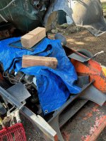
A FEW PICS
As has been the norm....trying to get the various parts to do things they were never meant to do can be a challenge....
But a bit of creativity and lots of midnight oil usually pays off.....
Grabbed a bunch of steel and other goodies to get things sort of where they needed to sit.
Clamped in some gen 2 and a gen 3 tire guides offset as far as they will get while sitting in the sprockets to get a good idea on what they have for clearance......
Not huge amounts.....but should be fine.....
If a track jumps off.....Could get ugly.......But that's not unusual anyway.....
The bearings, seals and a few other items are on the way.
Tube steel to machine the caliper mount is in the shop.....Drawings are about done for the first part.....We will see just how this all works.
2 inch shaft with a round plate welded on bolts to the sprocket.using existing lug nuts....(4 nuts directly to the sprocket every other but will bolt the brake shaft assembly)
Then a second disc welds to the shaft and hold the rotor....The caliper bracket and bearing assembly slip onto the shaft and is retained by a snap ring.....A seal on the inner end seals out water and crud.....The bearing is a 5210 2RS (Double sealed)
The plumbing will be simple....One high pressure line from the master cylinder and a divider to the brake calipers.....
This system will assure that we have brakes no matter what............
The stock S-Wagon master cylinder with the rear brake portion blocked off and the air bled out.....All good and an easy part to source if service parts are needed.......
I had considered a hydroboost.....no real need....The vacuum booster should be fine......
Spending time doing engineering on parts that need to be machined....
The hydraulic components are trickling in as the days go by....
A big thing that needed to get some serious design work done is the "Rear outboard disc brakes"
The 2100 was available with either a single brake pedal that was originally plumbed into the steering system and gave the operator the ability to apply the steering bands "Gently" for controlled braking.....
The original steering control valves are no longer available and the simple on/off controls that work fine for steering are a nightmare when trying to brake under sketchy situations......
The choices available are all complex.....
I decided to go with a stand alone disc brake set up that fastens to the track drive sprockets and is powered by the original hydraulic brake master cylinder and vacuum booster from the S Wagon.
Getting components that will fit and work have been an interesting journey.
The S Wagon 4x4 front disc brakes are easy parts to find and repair parts are plentiful.....
Now getting all the goodies to bolt in and then play well with the other kids on the block and not have a train wreck ....herein lies the fun part
I did some serious mock up and measuring....then got after finding parts that will allow the calipers and rotors to fit as though they had been intended to do so......
I have seen one other example of a similar set up and decided to make a slightly different adaptation ....
The mock up was done to get a good eye on where the track guides were going to run and what sort of room we had.
The brake calipers will face forward towards the #4 axle guide wheel.
The caliper mounts to a bracket that will fasten to the sprocket.
A 5210 bearing (Same as the axle shaft) will allow the caliper to be guided steady and not get out of sorts with the rotor....
A torque arm mounted to the bracket will transfer the braking reaction to the main frame of the cat.....
Spent the weekend running down parts, bits and pieces online and getting the engineering thrashed out.
Got some basic working drawings done so the parts can be machined......
I grabbed a fresh set of brake pads to allow getting the calipers in the sweet spot before mounting things.
Its a snug fit....but looks pretty decent.....
The brake rotors are 10-1/2 inch....not supper big by any means....should be plenty to stop things from 10-15 mph.....
A FEW PICS
As has been the norm....trying to get the various parts to do things they were never meant to do can be a challenge....
But a bit of creativity and lots of midnight oil usually pays off.....
Grabbed a bunch of steel and other goodies to get things sort of where they needed to sit.
Clamped in some gen 2 and a gen 3 tire guides offset as far as they will get while sitting in the sprockets to get a good idea on what they have for clearance......
Not huge amounts.....but should be fine.....
If a track jumps off.....Could get ugly.......But that's not unusual anyway.....
The bearings, seals and a few other items are on the way.
Tube steel to machine the caliper mount is in the shop.....Drawings are about done for the first part.....We will see just how this all works.
2 inch shaft with a round plate welded on bolts to the sprocket.using existing lug nuts....(4 nuts directly to the sprocket every other but will bolt the brake shaft assembly)
Then a second disc welds to the shaft and hold the rotor....The caliper bracket and bearing assembly slip onto the shaft and is retained by a snap ring.....A seal on the inner end seals out water and crud.....The bearing is a 5210 2RS (Double sealed)
The plumbing will be simple....One high pressure line from the master cylinder and a divider to the brake calipers.....
This system will assure that we have brakes no matter what............
The stock S-Wagon master cylinder with the rear brake portion blocked off and the air bled out.....All good and an easy part to source if service parts are needed.......
I had considered a hydroboost.....no real need....The vacuum booster should be fine......
Attachments


Last edited:
Snowy Rivers
Well-known member
Yeah...I hear ya.....But having the ability to stop the beast reliably is a real plus.
One of our past members "snowcatcrazy" had the 2100 with the full sized Chevy van on top was coming down a steep grade and was using the steering brakes only and had the thing get real HINKY and from what I gathered it came close to going off a ledge....
Flat ground is not a big worry.....But I want the ability to handle things.....
Also...With the OC-12...If there is an axle failure the bands will not stop the rig.....Other internal failures can also render the bands useless for stopping....
Here is his post from back in 2015
Having run a 2100 on the Mt Grooming I can say I was not real pleased with the brakes.....But one could drop the blade and dig it in.....
For a cruiser I Want the added control and for any novice operator that may happen....The natural reaction in a situation would be to stick the right foot on the brake pedal.....
Not really all that much work to get this done.....A bolt on option.....
I built the disk brakes pictured to better control my downhill speed. I nearly killed everyone in my cat last year coming down the mountain and nearly went off a 300 foot cliff ...that will not happen again!
Sent from my SM-G900P using Tapatalk
Like Reply
Report
The 603 I had and the tucker would come to a complete stop when the clutch pushed in within 10 feet. Even in 3rd gear and sit on a 20 degree incline without brakes. Someone was driving over there head and then panicked pulling brakes sending the cat left and right down a mountain, would be scary. Don't do that. On a steep crooked road I never go over 5-7 mph.
Snowy Rivers
Well-known member
Yessssss...I can see that very thing happening
Once you get things all hinky and go into panic mode.....yes ...I can see that happen.
These machines are not meant to fly and they don't handle like a sports car either....
The two 2100's I drove were both in new condition back in the day.....
On steep grades it was real easy to get in way over your head and quick too......
Not being to feather the brakes it only took one mistake and things got crazy ugly ion a hurry......
The best thing they ever did was when they went to the Hydrostatic drives.....Really easy to keep things well in check......
I had the one 2100 go sideways in a slide one night......Damned scary....Was a small avalanche that grabbed the machine and we went for one helluva ride.......
No big danger like drop offs or ???? just a long way to the bottom.....I managed to get the cat turned facing with the flow and finally worked it over to a place I could get out of the slide......
Couple other guys on the Mt saw it all happen and were coaching on the radio.....
Thanks troops......I was a nooby then.....Yup...earned my stripes that night....Needed a change or shorts too.
Anyway.....I am still planning on having the rear brakes......If the engine were to stop....there is nothing.
The smaller cats with the handle operated bands are no worry at all....They still work.
The 2100's were all hydraulic...unless you had the manual brake option.....
Snowy Rivers
Well-known member
Yes.......I had looked at that very idea....
Big problem...the drive shaft is too close to the bottom of the tub in the 2100 to get anything onto the shaft.
The 2100 has a completely enclosed chassis/tub.
The smaller machines are more open.
Ah well.
The current plan is coming together well....Plus it is a bolt on unit and does not alter the axle or other parts./....
I had the rotors, calipers and parts sitting on the shelf from another S-Wagon I parted out.
Give those things a job ....
Snowy Rivers
Well-known member
Sooooo
Design work done on the brakes......Parts list pretty much completed and items sourced....
The 5210 support bearings are here...
The plate steel rings to build the supports for the caliper mount were an issue (Needed 4 items for each assembly)
These need to be flat and true to size and NOT cut with the torch.....Decided to go with water jet cutting.
Finally found an outfit across town that quoted a decent price for time and materials....
Should have all that stuff in a week.....
In the interim I will get the 2 inch support shafts and machine them to accept the 5210 bearings....(90mmx50mmx30.2mm)
This is the same bearing as used on the axle shaft.....Decided to go with a double sealed/greased bearing....This will keep the assembly in good shape and keep the water and crud out.
Inner end of the tube gets a seal to make real sure things stay in good shape....
1/4" outer plate (Torque arm mount bolts to the caliper mounting tube and covers the outer end)
I have the outer caliper support tube (4" OD X 3-1/4" ID) Will cut these and machine them to finished length.
2 snap rings to retain the assembly on the shaft are ordered (Not an auto parts store size)
The UNIVERSAL caliper mount shown in the previous picture was designed to clamp to the rear axle on an S10 to convert to rear disc brakes.....SOME MODIFICATION REQUIRED to work on the cat.....
These brackets fit the caliper BUT were meant to work with the 11-1/4" rotor
The rotors on this set up are the stock 10-1/2" diameter.....That is why the bracket was cut and welded.....
The 10-1/2" rotor diameter allows the entire assembly to fit into the area in the track drive sprocket and not cause any serious issues with the tire guides and or ??????
A complete self contained bolt on unit that does not modify the sprocket and only requires the addition of a plate welded to the cat frame to hold the torque arm in place.......
I will get pics as this comes along.....
I can get some machine work done in the shop....But until the weather gets better....not much outside stuff happening....
Off topic, I know you were a truck driver. I am looking of an old axillary transmission, like a Brownie box or spicer unit. Do you have one or know where one is?Normally they have 2 under drives a 1:1 and an OD. Looking to couple it with a 5.9 cummins and Allison at545 automatic.
Snowy Rivers
Well-known member
Yesss
I was in the trucking Bizz for a lot of years
The auxiliary boxes .....I had a 1970 Pete with a 318 Detroit it had a 5 speed main box and a 4 speed "Brownie box"
The box in my rig was a DEEP UNDER....Then the other 3 were progressive.
My suggestion as far as locating one would be CRAIG'S LIST.....Truck salvage yards local to you.....
I have been out of that loop since 2013 and even then I was not really in the used market much.
My last rig has an 18 speed fuller in it
If you can score one that would give the project a real set of gears.
Good luck in the search..
Thanks anyway, had to askYesss
I was in the trucking Bizz for a lot of years
The auxiliary boxes .....I had a 1970 Pete with a 318 Detroit it had a 5 speed main box and a 4 speed "Brownie box"
The box in my rig was a DEEP UNDER....Then the other 3 were progressive.
My suggestion as far as locating one would be CRAIG'S LIST.....Truck salvage yards local to you.....
I have been out of that loop since 2013 and even then I was not really in the used market much.
My last rig has an 18 speed fuller in it
If you can score one that would give the project a real set of gears.
Good luck in the search..
Snowy Rivers
Well-known member
No worries...
Good luck on the search......There has to be one out there....
Good luck on the search......There has to be one out there....
Snowy Rivers
Well-known member
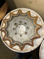
Back at the new brake setup while we wait for outdoor weather to show up....MORE SNOW FORECAST FOR MONDAY...
Decided to grab the 0C-12 Axle tube and slip the axle in to check out some measurements to be sure there were not going to be something to bite me in the azz later.
No measurement issues....BUTTTTTTTTTTTTTTTTTTTTT....A much different issue.
The OC-12 SAW CHANGES OVER THE YEARS
The original axle shafts were made with a snap ring to hold the axle bearing in place on the shaft......An easy set up to work on.....But the snap ring groove was a bad move and axles were known to snap off at the groove....(Predictable outcome)
Also the original set up had an inner seal near the outside end of the axle tube to keep excess oil from the diffy box and the drop boxes from flooding the axle bearing.....The axle bearing was greased.....A seal at the outer end just outside of the bearing and before the bolt flange.......(in the retainer plate)
The later axle shafts (The ones on this Diffy) did not have a snap ring....but instead used a press on retaining ring (Wedding band) to keep the bearing in place.
I had not done much more than a quick clean up of the axle tubes back when I removed the rear Diify.....
Ripped the axles out and removed one bearing to get numbers and to get the retainer plate off to get the seal numbers.
The bearing was in bad shape anyway........
The retaining ring appeared to have been made by a previous shop or ????? and was a bit too large and a tad too thick.
The ring had been chewing on the inside of the axle tube where the tube and the bearing housing are welded together.
Damage was minimal BUT was enough to chew up metal which had been the likely reason the bearing failed.
The 5210 bearing used was an open style which allowed the oil from the gear boxes to flow all the way to the outer seal....AND BACK TOO
The bearing had cracked the outer race and things just turned ugly.....Broken pieces had found their way back into the drop box and had damaged the outer bearing there too...
The center section is fully rebuilt now....But I had not reinstalled the axle tubes yet to keep the package a manageable size in the shop.....
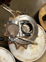
The 5210 bearing has a snap ring on the OD near the outer edge and the ring sits in a machined recess in the retaining flange (Piccy shows the inner and outer recesses in the flange)
The retaining ring shows the damage on the OD where it was rubbing...(I cut the ring to free it up so it would come off easy)
The inner bearing race looks like 50 miles of really bad road)
Soooooooo...
The issue......To reduce the oil into the axle bearing......
The bearing shown in the piccy is a double sealed grease filled unit I bought for the brake bracket assembly....To get a double sealed bearing with the snap ring on the OD is a spendy proposition $$$$$$$$$$$$$
Nobody in the area had this bearing and everything I found online with the double seal was also missing the ring.
Double shielded or open bearings with the ring were easy to find.
I will not reassemble this with open type bearings......The amount of oil that gets out there will find its way through the seal.
The seal in the flange had been beaten into the flange with a hammer....It is crooked in the bore and about 1/8th inch out on one side and slightly below on the other..
Seal had been leaking A LOT
Part of the reason was that the case vent on the Diffy was plugged......That did not help matters at all.....Plus this original design was set up to keep the bearing area in grease and not allowing oil to flow out from the diffy..
Solution
I decided after looking the axle tube over well and measuring all the parts.....That using a double sealed bearing without the snap ring was the trick.....The bore that is in the axle tube is machined to a depth approx. 7/8" deeper than where the bearing sits......But the depth is NOT the same on both axle tubes.....Close....and finished well.....but not to an accurate
spec......
OK
Answer is to machine a ring that can sit between the bottom of the bore and the bearing to allow the bearing to sit where it needs to and not slide in/out......
The rings will be custom fit......
The original plan likely was to keep the axle tube machining simple and make the retainer flange the part with the tight tolerance.....
I suspect that whoever was making the axle tube assemblies did not have a lathe large enough to handle these tubes after they were welded together and so the way they did the set up makes sense..
The axle tubes are a three piece assembly.. The outer bearing housing......the axle tube (Steel tube) and the inner housing that bolts to the OC-12
The parts are pressed together and then welded......Accuracy was not that critical.... plus/minus 1/16" OAL GOOD TO FLY
The mounting holes on the chassis are slotted so all would fit well......
Actually not a bad plan....but after the redesigns things just were not that great.
So both sides will get a custom spacer to go into bearing housing to locate the bearing and life will be good.
The double sealed bearing will keep the volume of oil from getting out to the outer seal and stop any issues..
Plus the cost of the bearings (And availability) will be a bunch better......
Spending several hundred $$$$$ on one bearing is not gonna happen.....The double sealed 5210 less the ring can be had for $35-50 each......Even US made ones....
The crowd that worked on this machine in the past were absolute butchers......5 pound hammer types....
So the brake assembly work actually brought this mess out into the open....Better now than later.....I have far more time to sit and measure parts....do the math and surf the web scouting out parts now than come good weather.......
One could ask.....What about the next folks who might work on this thing ????
The inner spacer rings are not the same by several Thousands of an inch and are not interchangeable......My best plan is to mark them RH and LH and mark the tubes.
I have a large binder with all the build info documented in great detail......If this machine falls into the hands of the 5 pound hammer crew in the future.....Oh well.....
I may make these spacers a really snug (Tap fit) so they wont fall out....Std bearings will always fit.....no worries.....
A look at the retaining ring picture 5954 you can see the sharp lip bured up...the metal crap caused the bearing to jam and the explode with pieces getting scattered
The cuts are where I relieved it during tear down.....
The bearing is sitting in the inner ring where it resides at assembly
Originally there was a gasket between the retainer and the axle tube bearing housing...
Will likely opt for HI TEMP silicone goop......Less hassle and good sealing
The inner race piccy shows the damage.....The outer race came off in chunks when the axle was slid out originally.
Axle tube assembly is fine.....Just a bit of cleaning and a couple burs and nicks to be cleaned up
The seal in the retainer plate is the old one (Left so I could grab the seal numbers 410316
Luckily the hammer crew did not destroy the seal beyond reading the numbers.....Made my life easier anyway.....
More fun stuff......
As the new parts get machined I will grab some pics and get them up
I started the new "Wedding bands" quite a while back.....They need the bores finished......About a .004"/.005" shrink fit.....
I think that adding a groove to be able to remove these would be a nice touch....Cutting them off is so DAMNED CRUDE
Decided to grab the 0C-12 Axle tube and slip the axle in to check out some measurements to be sure there were not going to be something to bite me in the azz later.
No measurement issues....BUTTTTTTTTTTTTTTTTTTTTT....A much different issue.
The OC-12 SAW CHANGES OVER THE YEARS
The original axle shafts were made with a snap ring to hold the axle bearing in place on the shaft......An easy set up to work on.....But the snap ring groove was a bad move and axles were known to snap off at the groove....(Predictable outcome)
Also the original set up had an inner seal near the outside end of the axle tube to keep excess oil from the diffy box and the drop boxes from flooding the axle bearing.....The axle bearing was greased.....A seal at the outer end just outside of the bearing and before the bolt flange.......(in the retainer plate)
The later axle shafts (The ones on this Diffy) did not have a snap ring....but instead used a press on retaining ring (Wedding band) to keep the bearing in place.
I had not done much more than a quick clean up of the axle tubes back when I removed the rear Diify.....
Ripped the axles out and removed one bearing to get numbers and to get the retainer plate off to get the seal numbers.
The bearing was in bad shape anyway........
The retaining ring appeared to have been made by a previous shop or ????? and was a bit too large and a tad too thick.
The ring had been chewing on the inside of the axle tube where the tube and the bearing housing are welded together.
Damage was minimal BUT was enough to chew up metal which had been the likely reason the bearing failed.
The 5210 bearing used was an open style which allowed the oil from the gear boxes to flow all the way to the outer seal....AND BACK TOO
The bearing had cracked the outer race and things just turned ugly.....Broken pieces had found their way back into the drop box and had damaged the outer bearing there too...
The center section is fully rebuilt now....But I had not reinstalled the axle tubes yet to keep the package a manageable size in the shop.....
The 5210 bearing has a snap ring on the OD near the outer edge and the ring sits in a machined recess in the retaining flange (Piccy shows the inner and outer recesses in the flange)
The retaining ring shows the damage on the OD where it was rubbing...(I cut the ring to free it up so it would come off easy)
The inner bearing race looks like 50 miles of really bad road)
Soooooooo...
The issue......To reduce the oil into the axle bearing......
The bearing shown in the piccy is a double sealed grease filled unit I bought for the brake bracket assembly....To get a double sealed bearing with the snap ring on the OD is a spendy proposition $$$$$$$$$$$$$
Nobody in the area had this bearing and everything I found online with the double seal was also missing the ring.
Double shielded or open bearings with the ring were easy to find.
I will not reassemble this with open type bearings......The amount of oil that gets out there will find its way through the seal.
The seal in the flange had been beaten into the flange with a hammer....It is crooked in the bore and about 1/8th inch out on one side and slightly below on the other..
Seal had been leaking A LOT
Part of the reason was that the case vent on the Diffy was plugged......That did not help matters at all.....Plus this original design was set up to keep the bearing area in grease and not allowing oil to flow out from the diffy..
Solution
I decided after looking the axle tube over well and measuring all the parts.....That using a double sealed bearing without the snap ring was the trick.....The bore that is in the axle tube is machined to a depth approx. 7/8" deeper than where the bearing sits......But the depth is NOT the same on both axle tubes.....Close....and finished well.....but not to an accurate
spec......
OK
Answer is to machine a ring that can sit between the bottom of the bore and the bearing to allow the bearing to sit where it needs to and not slide in/out......
The rings will be custom fit......
The original plan likely was to keep the axle tube machining simple and make the retainer flange the part with the tight tolerance.....
I suspect that whoever was making the axle tube assemblies did not have a lathe large enough to handle these tubes after they were welded together and so the way they did the set up makes sense..
The axle tubes are a three piece assembly.. The outer bearing housing......the axle tube (Steel tube) and the inner housing that bolts to the OC-12
The parts are pressed together and then welded......Accuracy was not that critical.... plus/minus 1/16" OAL GOOD TO FLY
The mounting holes on the chassis are slotted so all would fit well......
Actually not a bad plan....but after the redesigns things just were not that great.
So both sides will get a custom spacer to go into bearing housing to locate the bearing and life will be good.
The double sealed bearing will keep the volume of oil from getting out to the outer seal and stop any issues..
Plus the cost of the bearings (And availability) will be a bunch better......
Spending several hundred $$$$$ on one bearing is not gonna happen.....The double sealed 5210 less the ring can be had for $35-50 each......Even US made ones....
The crowd that worked on this machine in the past were absolute butchers......5 pound hammer types....
So the brake assembly work actually brought this mess out into the open....Better now than later.....I have far more time to sit and measure parts....do the math and surf the web scouting out parts now than come good weather.......
One could ask.....What about the next folks who might work on this thing ????
The inner spacer rings are not the same by several Thousands of an inch and are not interchangeable......My best plan is to mark them RH and LH and mark the tubes.
I have a large binder with all the build info documented in great detail......If this machine falls into the hands of the 5 pound hammer crew in the future.....Oh well.....
I may make these spacers a really snug (Tap fit) so they wont fall out....Std bearings will always fit.....no worries.....
A look at the retaining ring picture 5954 you can see the sharp lip bured up...the metal crap caused the bearing to jam and the explode with pieces getting scattered
The cuts are where I relieved it during tear down.....
The bearing is sitting in the inner ring where it resides at assembly
Originally there was a gasket between the retainer and the axle tube bearing housing...
Will likely opt for HI TEMP silicone goop......Less hassle and good sealing
The inner race piccy shows the damage.....The outer race came off in chunks when the axle was slid out originally.
Axle tube assembly is fine.....Just a bit of cleaning and a couple burs and nicks to be cleaned up
The seal in the retainer plate is the old one (Left so I could grab the seal numbers 410316
Luckily the hammer crew did not destroy the seal beyond reading the numbers.....Made my life easier anyway.....
More fun stuff......
As the new parts get machined I will grab some pics and get them up
I started the new "Wedding bands" quite a while back.....They need the bores finished......About a .004"/.005" shrink fit.....
I think that adding a groove to be able to remove these would be a nice touch....Cutting them off is so DAMNED CRUDE
Attachments

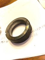
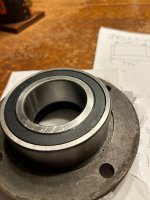

Last edited: