Snowy Rivers
Well-known member
Some nice spring like weather today and for another day or two.
The nasty winds, ice storm and other events left the cat covered with limbs, cones, needles and a big mess.
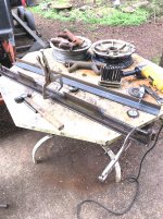
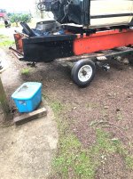
Decided to get the little tractor up to the house and get the cat pulled out of it's place in front of the shop and clean things up A LOT.
A couple pix.
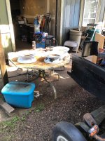
Cat pulled back out of the way....cleaned out all the crap that had accumulated over the winter.
We are actually starting year two of the resto/mod.
All the work that got accomplished last year actually amounted to a lot of progress.
All the old hydraulics and such removed.
Original tranny removed.
Chassis cleaned up
Small block Chevy procured along with a TH 350 TRANNY.
Power pack fit into chassis.
Exhaust all built and fitted.
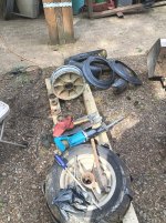
OC12 completely rebuilt
S10 pickup purchased to provide a cab and bed
Cab fitted and mounts built.
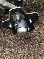
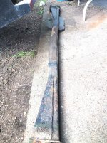
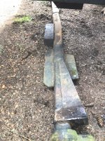
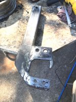
Front axle to be replaced with a hybrid type similar to the later style Thiokol 3700 axle..separate axles on each side.
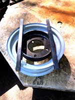
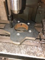
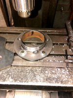
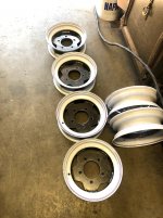
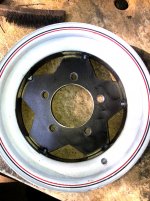
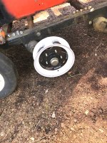
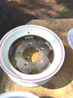
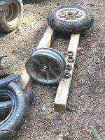
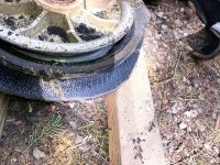
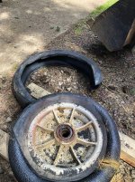
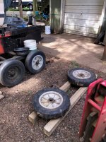
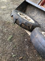
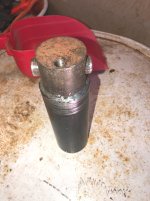
Currently have 4 of the alloy wheel hub combos....front and rear axles.
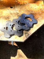
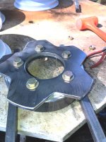
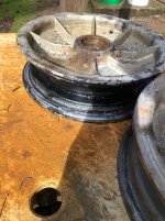
Wheels and custom centers on hand for the 6 center wheel locations.
Currently have a good Chevy 400 small block.... Crank, Rods (Just reworked).... Have a complete 1998 Chevy 350 Vortec.
Going to use the Vortec heads, Serpentine accessory drive and a few other goodies.
Bore the block .030" Oversize and wind up with a VORTEC 406.
Will likely sell the 305 that is sitting in the cat now.
TH350 will be kept...
As soon as the weather allows....will remove the cab and get after the drive shaft mounting and get the OC12 back into the cat.
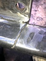
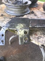
Small repair work needed on the outer diffy axle tube mounts at the frame.
Engine and tranny mounts need to have the finish welds done.. (Mounts are a slip to fit and weld type)
Ant eater nose Hood needs to be fabricated....
Looks like a front end similar to what the 2100 had originally will be the plan (Box tube assembly)
The pickup box from the S10 MAY GO ON THE REAR....UNLESS ANOTHER SIMILAR CAB CAN BE LOCATED.
A double cab would be nice.
A lot of work really has been done in this year.
The design for a set of 3 foot wide tracks is complete and will include the original 2100 tire guides...(We have nearly enough guides now to build two tracks)
Original track sprockets are so so....will get us going...they will need to be recovered at some point.
Getting outside today really got the Cat itch going again.....
The nasty winds, ice storm and other events left the cat covered with limbs, cones, needles and a big mess.
Decided to get the little tractor up to the house and get the cat pulled out of it's place in front of the shop and clean things up A LOT.
A couple pix.
Cat pulled back out of the way....cleaned out all the crap that had accumulated over the winter.
We are actually starting year two of the resto/mod.
All the work that got accomplished last year actually amounted to a lot of progress.
All the old hydraulics and such removed.
Original tranny removed.
Chassis cleaned up
Small block Chevy procured along with a TH 350 TRANNY.
Power pack fit into chassis.
Exhaust all built and fitted.
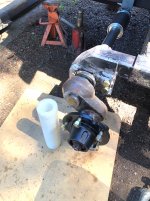
OC12 completely rebuilt
S10 pickup purchased to provide a cab and bed
Cab fitted and mounts built.
Front axle to be replaced with a hybrid type similar to the later style Thiokol 3700 axle..separate axles on each side.
Currently have 4 of the alloy wheel hub combos....front and rear axles.
Wheels and custom centers on hand for the 6 center wheel locations.
Currently have a good Chevy 400 small block.... Crank, Rods (Just reworked).... Have a complete 1998 Chevy 350 Vortec.
Going to use the Vortec heads, Serpentine accessory drive and a few other goodies.
Bore the block .030" Oversize and wind up with a VORTEC 406.
Will likely sell the 305 that is sitting in the cat now.
TH350 will be kept...
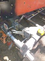
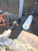
As soon as the weather allows....will remove the cab and get after the drive shaft mounting and get the OC12 back into the cat.
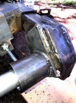
Small repair work needed on the outer diffy axle tube mounts at the frame.
Engine and tranny mounts need to have the finish welds done.. (Mounts are a slip to fit and weld type)
Ant eater nose Hood needs to be fabricated....
Looks like a front end similar to what the 2100 had originally will be the plan (Box tube assembly)
The pickup box from the S10 MAY GO ON THE REAR....UNLESS ANOTHER SIMILAR CAB CAN BE LOCATED.
A double cab would be nice.
A lot of work really has been done in this year.
The design for a set of 3 foot wide tracks is complete and will include the original 2100 tire guides...(We have nearly enough guides now to build two tracks)
Original track sprockets are so so....will get us going...they will need to be recovered at some point.
Getting outside today really got the Cat itch going again.....