-
Please be sure to read the rules and adhere to them. Some banned members have complained that they are not spammers. But they spammed us. Some even tried to redirect our members to other forums. Duh. Be smart. Read the rules and adhere to them and we will all get along just fine. Cheers. :beer: Link to the rules: https://www.forumsforums.com/threads/forum-rules-info.2974/
You are using an out of date browser. It may not display this or other websites correctly.
You should upgrade or use an alternative browser.
You should upgrade or use an alternative browser.
Astro van cat conversion
- Thread starter Snowy Rivers
- Start date
Snowy Rivers
Well-known member
THANK YOU.....
I have been on the Diesel Pickup boards since 2001 and am currently one of the mods at "The Diesel Page".....We see all kinds go through...
I am not offended by this type of post....but do find that it raises a big question ?????????????? WHY do people hide behind their computer and make caustic comments about the work and efforts of others......??????
I scanned this other persons list of posts on this venue, VERY limited input.
Does not appear that they have, or have had a cat.......
Few people realize just what sort of work is involved to even do a basic renovation on a cat using stock parts......let alone whats involved when you get into the depths of trying to design "new parts" and then procuring materials to manufacture said parts, or to modify an existing item to work and maybe do what is needed.
Our troopers here that own these ancient cats (Scrap iron)know all too well about the "Roll your own projects"
To make a statement/statements as has been posted about the number of pages as compared to how far along this project is really baffles me.
I spend probably 10 x more physical time researching, figuring (Imagineering) and doodling on paper with my tape measure, digital calipers and such in hand compared to the time out at the cat welding, machining and assembling.
That S10 cab did not jump onto the cat chassis, the new front axle assembly did not come in a box left on the the stoop by THE LITTLE BROWN TRUCK ......
My hat is off to anyone that is willing to step up to the plate and take on even the most basic of rebuilds on one of these old piles of rusty gold.
If not for having the Mill and the lathe in the shop.....I would not have started this project.
Hiring out custom build to suit parts would be so costly.....one could go buy a good used "turn key" machine.
As all of you folks here know ....these cats are a labor of love.......
Some days I may only sit and make sketches to get an idea worked out.....and or possibly make one little part.....But it is satisfying when it comes together.....
I have seen some folks here drag home the most gawd awful looking stuff and turn it into a thing of beauty......This puts a smile on my face...EVERY TIME..... I see the blood sweat and tears that went into these projects.....and appreciate the long hours and the hard labor that went into it..
To the person who can hide behind their computer and write caustic abbreviations on a post and make critical comment of the hard work of others.
I have an abbreviation for Y'all.......Not very lady like...so I will refrain from posting it......Let the imagination fill in the blanks....
Thank you troops for the help, the "Likes" and the comments.....
Yeah....Maybe my posts can get a tad on the WTMI side....But someone out there may well find a useful tid bit that will help them.
This forum is like a family, we all share a common interest...( Likely many) and have lives to live off these pages.....Some of us are retired, others have a day job...... I see many with children.......
The amount of effort it takes these days to just survive in this age of a pandemic and other crap going on sure takes it's toll......
Rant off
I really don't think I'm hiding behind anything; I'm a long standing member of the forum and was just expressing my opinion, the purpose of a forum or am I wrong? and the fact that I really haven't read all the posts on this thread and the fact that his/her first reply is almost a full page of this thread attests to my use of TMI. I've been a member here for 14 years and in that time I've owned and sold a 53 743 Freighter and 2 Imps here so, so much for your research talents. I come here to gain USEFUL information, not life stories so much especially in the Snowcat Repair and Restoration area of this forum.To quote someone famous " keep it pithy".... Reply off, rather than, rant off....Bob
vintagebike
Well-known member

Snowy Rivers
Well-known member
Well Bob.
As mentioned...This ain't twitter...Tain't face book either....
But...You are certainly welcome to come and help...... I can always use an extra pair of hands.
You run a Bridgeport ???? mig Weld, spin the knobs on a lathe ????
I have old school tools....Not the fancy CNC stuff mind ya
I do ramble on a lot....I have even been known to talk to myself while I work too.....Surprising the good answers I get....
Yeah buddy....
Last edited:
Snowy Rivers
Well-known member
Anyway...
Back to the build.
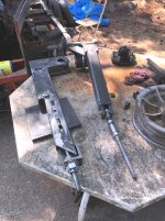
Today was a productive day....
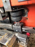
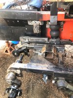
Got the air bag arm fit with it's hub, the hub located and the axle set at the proper full down position....The unit welded up.
Installed the assembly (Less the air bag and the lower perch.
The bag will be soon to get bolted in and things fitted up
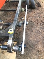
After the assembly was fit I tossed the straight edge back on the wheel hubs to check the location....
Still a ways to go....but we are gaining ground......
Pics show pretty much the details.
The threaded puller holes can be seen in the bag arm hub.
Yeah Bob.....No hard feelings....Just do come and help....always can use a hand
Back to the build.
Today was a productive day....
Got the air bag arm fit with it's hub, the hub located and the axle set at the proper full down position....The unit welded up.
Installed the assembly (Less the air bag and the lower perch.
The bag will be soon to get bolted in and things fitted up
After the assembly was fit I tossed the straight edge back on the wheel hubs to check the location....
Still a ways to go....but we are gaining ground......
Pics show pretty much the details.
The threaded puller holes can be seen in the bag arm hub.
Yeah Bob.....No hard feelings....Just do come and help....always can use a hand
Attachments


Snowy Rivers
Well-known member
Weather closed in this morning....I do not want the new unpainted parts rusty....
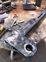
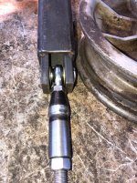
Managed to get the inner axle cap machined up.....
But today is likely going to be a bust.....
Here is the LH axle cap pics
Nothing much of great interest.....But it's a part that has to be there..
It not only covers the axle end to prevent damage, but it is a tool as well to help get the air bag arm shoved into place so the through bolt can be installed...
It is either that or whack on the arm with the soft hammer.....messes up the paint....
Attachments
Snowy Rivers
Well-known member
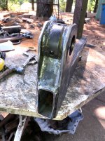
Weather was wonderful today....
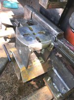
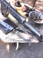
Got after the bag perch on the LH side
Had to machine the perch tad to make up for the slight anomaly in the stack....
All welded up, drilled and sitting in astraddle of the bag arm.
Tomorrow the spacers that align the perch and keep it centered on the arm get cut, machined and welded into the perch.
Threaded in a couple pieces of thread rod to line the bag up as it sits....Measured for the spacers....
A few pics...
Bob has not been over to help yet ......Sad deal.....I would love some company.....
Ah well....such is life....
Attachments

Snowy Rivers
Well-known member
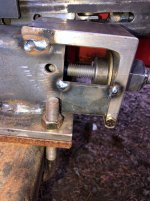
I was able to get more done on the LH axle today
The bag perch is finished now....(Inner spacers machined and welded in place)
The adjust nut bracket machined and the nut assembly in place and tack welded....
The bag perch adjuster slide is complete now.....
Things will need to wait until the arm can come off to weld the adjust nut assembly in place.
I got a call this morning from the fella I got the tracks from....He has some 2100 rear axle shafts (Spares) and some large bearing aluminum wheels with excellent tires.
Caveat with the wheels....there are 3 wheels in all with bearings that went to hell....The bearing bores are damaged....
Sooooooooooooooooooooo..
Going to make a fixture and place the tire/wheel assembly on the mill and bore the damaged area out and fit a sleeve.....
This may be a tad tedious to get things set up........Hopefully......there will be at least the dust cover bore still good to indicate things in and get to a reference point.
Good winter project when I can't work outside.
Putting the factory large bearing alloy wheels and tires on the four outer corners should work well.....
The custom snowflake wheels I built can fill in the center 6 places
Slowly this big beast is coming together.......
Attachments


Snowy Rivers
Well-known member
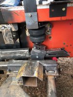
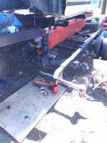
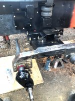
Finished getting the air bag bolted to the bracket and the lower perch bolted on.
Got the Street L and the schrader valve threaded into the air bag....
Everything fits as it should.
Notice on the one picture.....There is a white mark on the inner track adjuster slide tube.
The center of the bolt in the lower bag perch needs to line up with the line (Will be marked on the tube) when the track is adjusted.
This places the air bag in the proper position to be able to function through the arc of the arm under operating conditions.
Simply turning the large nut assembly at the rear of the bag arm slides the perch fore and aft on the arm in the slot.
Once things are in the sweet spot the jam nut is tightened up..(Jam nut not on the threaded rod yet)
Attachments

Snowy Rivers
Well-known member
Getting close now.
Pulled the axle shaft out and removed the inner track adjuster unit.
Installed the Heim joint and threaded adjuster rod and stuffed things back together.
Finished up the nut assembly....then machined the bracket that holds the nut assembly.
Got the rod threaded into the nut and then mounted the bracket and tack welded it.
Yanked all the stuff back off.
Tomorrow the last of the welding gets done on the track adjuster and air bag arm parts.
Then its time to rip the entire pile of goodies off the chassis....Clean it and get paint on it.
Once the paint is on and dry the entire package can go together for the last time.
Weather still looking good for a few more days....then there is rain showers showing up in the long range forecast.
I want this axle thing all done before rain flies.....
After that axle is finished....not sure just what we will head into next.
I would like to get the driveshaft finished....but the rear diffy needs to go back in before the shaft can be done...
Rather late in the season to drag the diffy back out....
When it goes in I want to leave it there.
I still need to get the one axle bearing off the axle and then clean it up.....
I machined the "Wedding bands" to hold the bearings back last year....I still need to bore them and get them ready to heat up and drop onto the shaft.
For now we shall take it one day at a time......
See what the weather does and fit in little projects as we can.....
This total rebuild of the front axle has taken far longer then I had imagined it would.
But all considered.....One helluvalot of design work, let alone the fabrication and machining.....
Lets just hope that it works well.....
Attachments
Snowy Rivers
Well-known member
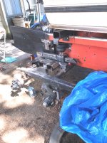
Definitely got at it today.
Ripped the entire LH axle assembly off the cat.
Washed the side of the tub down to get the old orange paint acceptable to shoot some black on it...at least to a point behind the new front axle suspension.....
Finished the welding on the inner track adjuster tube and the air bag arm perch adjuster.
Washed all the parts up to get off all the anti spatter spray and any other crap that will keep the paint from sticking.....
Shot the parts with some gloss black....
Let the paint dry while I ran to town to get a few last minute fasteners I wanted to replace.....Nylock nuts, some lock washers, and some other grade 8 hardware for the final assembly (I had used a lot of used trashy bolts for the preliminary setup and assemblies.
All fresh grade 8 stuff this trip around.
Still need to slip the outer tack adjuster out, wash it up and paint it....
The axle was in a perfect spot to shoot some paint on the spindle casting......
While the outer adjuster paint is drying I will assemble the grease cylinder, the hose and other stuff....Then put that assembly together.
Once the outer unit is all in....The shaft, thrust washers, the air bag arm and such can all go back on.
The only part left to make is the little split spacer tube that goes between the two center thrust washers.....
The cool little clamps are here now.....Still in the Amazon baggy.....
Late tomorrow....maybe into the weekend and the front axles will be finished....
Have not heard back on a time frame to pick up the large bearing alloy wheels/tires.
The story is that there are 3 of them that lost bearing/s
I do not know the extent of the damage.
Possibly the seal area is all that is damaged.?????
One of the original hubs on this machine had lost a bearing....and the seal was torn out and the seal bore fouled...
Dealing with boring the hub bores will be interesting with a tire on the wheel (Filled tires)
But I did haul one of my wheel/tire assemblies into the shop and toss it on the mill table.....A repair is doable....a little "Squaring and jigging" should gitterdone....
Worth the time and effort for sure.
If all goes well I should end up with 6 of the aluminum large bearing wheels/tires.
Fill in the rest with my custom snowflake wheels......
Gonna be sweet to get this old girl back up on all of it's wheels.......
Thinking seriously about yanking the 305 and the TH350 back out for the winter and getting the Tranny in on the bench.
Good job for winter...going through the gearbox.
Gotta snoop about and find my tranny tools.
Pump pullers, bushing drivers.....and other special tools....
Decided to make this a select shift (Full manual box) Dash 3 shift kit will get that......
The extremely low butt gears will be a royal PITA trying to calibrate the governor and the modulator to work worth a damn....Just make it a select shift...... More like the big farm tractors....
Still need to think through the output shaft and tail house area to sort out keeping the slip yoke on the drive shaft from moving in and out......
Will depend on how the center support on the double/double shaft assembly all comes together.....
The drive shaft is from an S10 extreme (Extended cab)
Short SHAFT at the tranny with a single cardan joint at the slip yoke...then the center support bearing and then a double cardan joint....the rear tube and then another double cardan joint with a bolt on flange that adapts to the custom pinion flange I machined up...
The double double will make life real forgiving as far as the drive line angles.....Looks like about 2 degrees at the single and then the rest will fall into place....A small angle at each connection will make everybody happy..
I have never run a double double before.
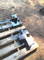
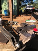
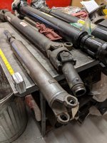
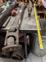
A couple pics of the shaft assembly
The short section gets cut and a pretty good chunk taken out.....The other shaft is the double double....Slip yoke on one end and the bolt on flange on the other.
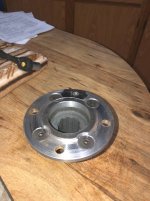
The new pinion flange is a modified unit from an M211 GMC Deuce and a half (1953 vintage)
The nice thing about the double double shaft is that the regular rules governing U JOINTS and shafts can be tweaked a lot and things still run smooth.
Just for anyone not familiar with the term "Double cardan joint" (Constant velocity)
Biggest issue with these bad boys is the centering ball must be greased every so often or the ball wears out and then the beast will shaker your azz out of the seat......
This shaft uses the GM 3R U JOINTS....and the centering ball, spring and other goodies all come in a handy little kit to allow easy R&R
The pinion flange adapter was a NOS part still in the original box from the army.
The mods needed to fit the OC-12 were minimal
Removed the oil slinger and shortened the snout about 1/4"
Splines were identical....Made the swap a walk in the park....
Had to relieve the area around the pinion nut a skosh....no worries.
Ripped the entire LH axle assembly off the cat.
Washed the side of the tub down to get the old orange paint acceptable to shoot some black on it...at least to a point behind the new front axle suspension.....
Finished the welding on the inner track adjuster tube and the air bag arm perch adjuster.
Washed all the parts up to get off all the anti spatter spray and any other crap that will keep the paint from sticking.....
Shot the parts with some gloss black....
Let the paint dry while I ran to town to get a few last minute fasteners I wanted to replace.....Nylock nuts, some lock washers, and some other grade 8 hardware for the final assembly (I had used a lot of used trashy bolts for the preliminary setup and assemblies.
All fresh grade 8 stuff this trip around.
Still need to slip the outer tack adjuster out, wash it up and paint it....
The axle was in a perfect spot to shoot some paint on the spindle casting......
While the outer adjuster paint is drying I will assemble the grease cylinder, the hose and other stuff....Then put that assembly together.
Once the outer unit is all in....The shaft, thrust washers, the air bag arm and such can all go back on.
The only part left to make is the little split spacer tube that goes between the two center thrust washers.....
The cool little clamps are here now.....Still in the Amazon baggy.....
Late tomorrow....maybe into the weekend and the front axles will be finished....
Have not heard back on a time frame to pick up the large bearing alloy wheels/tires.
The story is that there are 3 of them that lost bearing/s
I do not know the extent of the damage.
Possibly the seal area is all that is damaged.?????
One of the original hubs on this machine had lost a bearing....and the seal was torn out and the seal bore fouled...
Dealing with boring the hub bores will be interesting with a tire on the wheel (Filled tires)
But I did haul one of my wheel/tire assemblies into the shop and toss it on the mill table.....A repair is doable....a little "Squaring and jigging" should gitterdone....
Worth the time and effort for sure.
If all goes well I should end up with 6 of the aluminum large bearing wheels/tires.
Fill in the rest with my custom snowflake wheels......
Gonna be sweet to get this old girl back up on all of it's wheels.......
Thinking seriously about yanking the 305 and the TH350 back out for the winter and getting the Tranny in on the bench.
Good job for winter...going through the gearbox.
Gotta snoop about and find my tranny tools.
Pump pullers, bushing drivers.....and other special tools....
Decided to make this a select shift (Full manual box) Dash 3 shift kit will get that......
The extremely low butt gears will be a royal PITA trying to calibrate the governor and the modulator to work worth a damn....Just make it a select shift...... More like the big farm tractors....
Still need to think through the output shaft and tail house area to sort out keeping the slip yoke on the drive shaft from moving in and out......
Will depend on how the center support on the double/double shaft assembly all comes together.....
The drive shaft is from an S10 extreme (Extended cab)
Short SHAFT at the tranny with a single cardan joint at the slip yoke...then the center support bearing and then a double cardan joint....the rear tube and then another double cardan joint with a bolt on flange that adapts to the custom pinion flange I machined up...
The double double will make life real forgiving as far as the drive line angles.....Looks like about 2 degrees at the single and then the rest will fall into place....A small angle at each connection will make everybody happy..
I have never run a double double before.
A couple pics of the shaft assembly
The short section gets cut and a pretty good chunk taken out.....The other shaft is the double double....Slip yoke on one end and the bolt on flange on the other.
The new pinion flange is a modified unit from an M211 GMC Deuce and a half (1953 vintage)
The nice thing about the double double shaft is that the regular rules governing U JOINTS and shafts can be tweaked a lot and things still run smooth.
Just for anyone not familiar with the term "Double cardan joint" (Constant velocity)
Biggest issue with these bad boys is the centering ball must be greased every so often or the ball wears out and then the beast will shaker your azz out of the seat......
This shaft uses the GM 3R U JOINTS....and the centering ball, spring and other goodies all come in a handy little kit to allow easy R&R
The pinion flange adapter was a NOS part still in the original box from the army.
The mods needed to fit the OC-12 were minimal
Removed the oil slinger and shortened the snout about 1/4"
Splines were identical....Made the swap a walk in the park....
Had to relieve the area around the pinion nut a skosh....no worries.
Attachments
-
 LH PAINT READY5.jpg488.3 KB · Views: 99
 -
 LH PAINT READY4.jpg443.7 KB · Views: 102
 -
 LH PAINT READY2.jpg606.1 KB · Views: 94
 -
 LH PAINT READY3.jpg466.9 KB · Views: 98
 -
 LH PAINT READY1.jpg467.5 KB · Views: 99
 -
 ADAPTER9.jpg312.6 KB · Views: 106
 -
 ADAPTER11.jpg299.2 KB · Views: 98
 -
 IMG_1977.JPG314.3 KB · Views: 102
 -
 IMG_1978.JPG329 KB · Views: 105
 -
 CV ASSEMBLED4.jpg325.6 KB · Views: 99
Last edited:
Snowy Rivers
Well-known member
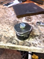
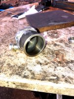
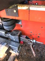
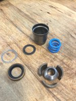
Got the outer track adjuster (Original with grease cylinder) put together and the assembly installed...
The LH grease cylinder was the original type....
Story on the cylinder is about like many things I found on this cat....Real Fubar.
The V packing seal was torn to rat crap....and some clown had been pumping grease into things until hell wouldn't have it.
The entire LH frame rail was stuffed full of grease.....(I am not exaggerating either....That bad boy was stuffed.....
The issue was one of poor knowledge and they would have been better off if they had left the hammer in the tool box...
The lip seal was chopped badly.......The snap ring groove is sharp and the seal slides in and the inner edge of the groove catches the seal.....
No way to slip a "Slider" between the seal and the cylinder to shoe horn the sucker in.
I tossed the cylinder in the lathe and run a boring bar in and tapered the inner edge of the ring groove out into the bore to allow the seal to slide on in without cutting the lip.
Polished the area really well to make things go.....
The piston slid right in.....removed it and double checked the seal.....
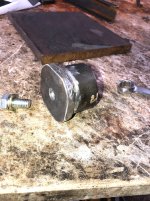
Getting the parts back on.
The air bag arm is ready to go on now.....
Checked the location of the assembly with the cylinder fully closed (Adjustment at "0" )
For some reason the assembly is 5/8" farther forward that the RH side...
Hmmmmmmmmmmmmmmmm
All the slider parts and such, the cylinder back head and everything I can measure are the same.
The cylinder on the LH side definitely had been off/replaced.....
I kept the parts with each cylinder together.....I did not have the cylinders close to each other....but I suspect the rod in the LH side may be a skosh longer.
5/8" is not gonna kill things....Just Odd that there is that much difference......
I will assume that the track adjuster runs about in the middle of it's travel when the track is happy..??????
With this machine it does not surprise me at all.....
A piccy as we stand as of this evening....
The LH grease cylinder was the original type....
Story on the cylinder is about like many things I found on this cat....Real Fubar.
The V packing seal was torn to rat crap....and some clown had been pumping grease into things until hell wouldn't have it.
The entire LH frame rail was stuffed full of grease.....(I am not exaggerating either....That bad boy was stuffed.....
The issue was one of poor knowledge and they would have been better off if they had left the hammer in the tool box...
The lip seal was chopped badly.......The snap ring groove is sharp and the seal slides in and the inner edge of the groove catches the seal.....
No way to slip a "Slider" between the seal and the cylinder to shoe horn the sucker in.
I tossed the cylinder in the lathe and run a boring bar in and tapered the inner edge of the ring groove out into the bore to allow the seal to slide on in without cutting the lip.
Polished the area really well to make things go.....
The piston slid right in.....removed it and double checked the seal.....
Getting the parts back on.
The air bag arm is ready to go on now.....
Checked the location of the assembly with the cylinder fully closed (Adjustment at "0" )
For some reason the assembly is 5/8" farther forward that the RH side...
Hmmmmmmmmmmmmmmmm
All the slider parts and such, the cylinder back head and everything I can measure are the same.
The cylinder on the LH side definitely had been off/replaced.....
I kept the parts with each cylinder together.....I did not have the cylinders close to each other....but I suspect the rod in the LH side may be a skosh longer.
5/8" is not gonna kill things....Just Odd that there is that much difference......
I will assume that the track adjuster runs about in the middle of it's travel when the track is happy..??????
With this machine it does not surprise me at all.....
A piccy as we stand as of this evening....
Attachments

Snowy Rivers
Well-known member
Pretty well wrapped up the LH front axle this morning.
Just need to grease up the center spacer tube ( Halves ) and get the Stainless steel clamps on..
A friend stopped by and we had good chat session.
The subject of using the Astro van on the cat came up......
We beat on that subject a bit.....I am still quite interested in that combination.....
I have have thought about the work involved to get the van up on the cat.....
I may have an idea to simplify that plan.......
I put an ad on Craigs to see if anything with a dead engine/tranny is out there dirt cheap...
At this point....it's at least worth exploring the idea again.....
The only down side is the limited access for maintenance......
We shall see....
Snowy Rivers
Well-known member
Sitting here crunching some numbers on the Idea of fitting the Astro body to the cat.
WEIGHT is a big concern.
Removing the original front sub frame.
ENGINE
TRANNY
SUSPENSION
TIRES/WHEELS
Radiator (Original)
The drive shaft
Rear axle & springs
Best guess seems to indicate this will shed about 2000 lbs
Keeping the fuel tank in the body is not a bad plan....
Lifting the body up so the cat can be rolled under it may be a lot easier than I had figured.
CAMPER JACKS on a temporary set of tubes attached to the underside of the body may well simplify the task greatly.
With the sub frame gone from the front will really open up things.
The front bumper normally mounts to the sub frame.....but could easily attach to a bracket on top of cat tub......
Just thinking outside the box a bit here......
Snowy Rivers
Well-known member
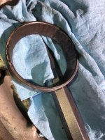
LH Front suspension is done.....So both of the front axles are now completed.
Decided to get the original aluminum front wheels out and cleaned up.....Knocked out the old bearings.
The bearings were as ugly as 25 miles of death valley fire trail.
A few pics of the races....These were just about to the stage where they start to inhale themselves and then chew up the hub....
All the bearings are being replaced....
I wanted to get well greased bearings and fresh seals on all the spindles.
The front tires are nothing to write home about....but they will be fine until we are ready to install the tracks.
Actually they would be OK for a few short test runs....
Side walls are sad....but they are filled...
The 3rd hub on the LH side had the nasty looking bearings....also the lug studs had been replaced with 9/16" studs and they were not even tight in the hub.....So the PO welded them in (Cast iron hub...yeah right)
I tossed that mess in the trash and replaced with new.
Spindle was perfect.....installed new hub, bearings and seal.
Still need to freshen up the last two hubs on the LH side.....
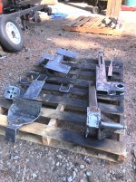
The alloy wheel/tire sits on a pallet with the bearings removed....Ready for the new races to go in and then pack the bearings with grease and assemble them....
Ran out of cotter pins......The last two I took apart had bent nails in them....GAWD.
Will see if anything can be had tomorrow.....Gonna get a handful of spares and toss on the shelf in the spares dept.
Going to get the rest of the hubs refreshed and then move on....
The one custom wheel on the number 3 axle LH side....
Need to start scaring up some tires......
SOOOOOO
All the spindles are in good shape....The last ones that are untouched as yet all need new bearings, but are not to the point of chewing themselves up....
I think a couple actually spin fairly quiet.....All getting replaced anyway....
The two fronts will need speedi sleeves on the seal rides....Pretty nasty groove worn in the ride.... Speedi sleeves will make them like new again.......
Decided to get the original aluminum front wheels out and cleaned up.....Knocked out the old bearings.
The bearings were as ugly as 25 miles of death valley fire trail.
A few pics of the races....These were just about to the stage where they start to inhale themselves and then chew up the hub....
All the bearings are being replaced....
I wanted to get well greased bearings and fresh seals on all the spindles.
The front tires are nothing to write home about....but they will be fine until we are ready to install the tracks.
Actually they would be OK for a few short test runs....
Side walls are sad....but they are filled...
The 3rd hub on the LH side had the nasty looking bearings....also the lug studs had been replaced with 9/16" studs and they were not even tight in the hub.....So the PO welded them in (Cast iron hub...yeah right)
I tossed that mess in the trash and replaced with new.
Spindle was perfect.....installed new hub, bearings and seal.
Still need to freshen up the last two hubs on the LH side.....
The alloy wheel/tire sits on a pallet with the bearings removed....Ready for the new races to go in and then pack the bearings with grease and assemble them....
Ran out of cotter pins......The last two I took apart had bent nails in them....GAWD.
Will see if anything can be had tomorrow.....Gonna get a handful of spares and toss on the shelf in the spares dept.
Going to get the rest of the hubs refreshed and then move on....
The one custom wheel on the number 3 axle LH side....
Need to start scaring up some tires......
SOOOOOO
All the spindles are in good shape....The last ones that are untouched as yet all need new bearings, but are not to the point of chewing themselves up....
I think a couple actually spin fairly quiet.....All getting replaced anyway....
The two fronts will need speedi sleeves on the seal rides....Pretty nasty groove worn in the ride.... Speedi sleeves will make them like new again.......
Attachments


Snowy Rivers
Well-known member
PJL
I thinks so too....at least from the perspective of the extra room.
The one issue that worries me is having access to pull maintenance on things.
The doghouse cover will allow some access to the rear of the engine....Not sure how possible it's going to be to get at the front of the engine for things like the serp belt.......
With the sub frame removed there will be more room under the front end.
Just thinking a bit here......
Can't say for absolute sure...BUTTTTTTTTTTTTTTT...There may be a way to turn the front sheet metal into a full tilt forward.
The outer fenders, inner fenders and the core support are all bolted together to form a unit assembly that sits on the core support up front via the biscuit mounts.....
Cut the fenders loose from the front of the body and add a light tube structural member as close to the firewall as possible to stabilize the fenders.....
Fasten the hood to the fender and core support unit.
Do a similar ditty low on the outer fenders and cut then on a 45 degree slice to allow the unit to clear as it tilts forward.
I SEE THAT SOME RESEARCH IS NEEDED TO SEE WHERE THE ASTRO COMES APART AND THEN CHEW ON HOW IT CAN BE DONE......
RAT ROD STYLE
With the engine in the belly of the 2100 tub and the radiator is 19" high ...this will (24 wide x 19 high cross flow )
Should be able to keep enough area up front to allow the tilt front end to be able to open far enough to allow good access to the engine.
Bottom line.
Any major work....the body is going to need to come off......
Definitely sounds interesting
Snowy Rivers
Well-known member
Headed back to the RH side and got the Front wheel/hub assembly washed up....Bearings all replaced and stuffed back onto the spindle.
Between interruptions, I managed to get the number two hub off and gone through as well....Again, bearings look like a lot of bad road....
Spindles are sweet.
Ripped off the number 3 hub....got it stripped out and ready to buff off the rust and crud.
Again...bearings JUNK.
I ran out of wheel bearing grease....need to get more.
The number 3 had some baling wire where the cotter pin should be....
Just sad what some folks try to get away with.
I mean...out in the sticks....anything that will get ya home is fine....But this machine was a 5 alarm train wreck all over....
So the number 4 hub is all that's left on the RH side....I replaced #5 hub last summer.....It was shot.....lug stud holes FUBAR'D
LH side still needs 4 and 5 to be reworked....They are noisy...but not trashed.
I bought enough new bearings and seals to redo all of the hubs....GOOD TO GO.
Why not just use 1" sq. tube, to build a cab that fits and tilts then skin it, similar to the original, but in any shape you desire.PJL
I thinks so too....at least from the perspective of the extra room.
The one issue that worries me is having access to pull maintenance on things.
The doghouse cover will allow some access to the rear of the engine....Not sure how possible it's going to be to get at the front of the engine for things like the serp belt.......
With the sub frame removed there will be more room under the front end.
Just thinking a bit here......
Can't say for absolute sure...BUTTTTTTTTTTTTTTT...There may be a way to turn the front sheet metal into a full tilt forward.
The outer fenders, inner fenders and the core support are all bolted together to form a unit assembly that sits on the core support up front via the biscuit mounts.....
Cut the fenders loose from the front of the body and add a light tube structural member as close to the firewall as possible to stabilize the fenders.....
Fasten the hood to the fender and core support unit.
Do a similar ditty low on the outer fenders and cut then on a 45 degree slice to allow the unit to clear as it tilts forward.
I SEE THAT SOME RESEARCH IS NEEDED TO SEE WHERE THE ASTRO COMES APART AND THEN CHEW ON HOW IT CAN BE DONE......
RAT ROD STYLE
With the engine in the belly of the 2100 tub and the radiator is 19" high ...this will (24 wide x 19 high cross flow )
Should be able to keep enough area up front to allow the tilt front end to be able to open far enough to allow good access to the engine.
Bottom line.
Any major work....the body is going to need to come off......
Definitely sounds interesting
Snowy Rivers
Well-known member
I have thought of that
Honestly
I am just not up to a redesign and build on a cab
Took me all summer to build the two axle units
Using a ready made (S10 cab or Astro van has everything plug and play pretty much )
Honestly
I am just not up to a redesign and build on a cab
Took me all summer to build the two axle units
Using a ready made (S10 cab or Astro van has everything plug and play pretty much )
Snowy Rivers
Well-known member
Took some time and sorted through all the tires and wheels I have accumulated through trades.
Looks like there are enough JUNK to get something "Black and round" on all 10 positions.
The two fronts are Falline filled tires....nothing to write home to mom about....but will be fine for the rest of the build and some testing.
The remainder of the stuff that came on the cat were air fill tires.....The wheels are crap....probably just clean the wheels and shoot them with silver paint for now..
There are a couple "Snow cat special" tires only....Nott too bad.....May toss them on a couple of my home brew wheels to fill up the remaining spots.
Looking at the various options on tires.
There are some nice looking 10 ply radials in 12" that are pretty much the same as the 5.30 x12 stockers
Whatever ends up will be filled on the front locations.....
Still waiting to see what shakes out on the alloy wheels with tires that lost bearings....
Nothing shaking as yet....
Still fooling about doing R & R on the remaining hubs and bearings.....
Nothing really exciting at this point.....
Last edited:
vintagebike
Well-known member
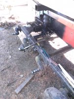
A trailer fabricator in Boise built this aluminum body on top of a Cushman Trackster for our "doodlecat'. That's a 1958 Trackmaster 4VL idling in the background.
Gutting it all out for a nice fit plus mounting it will be more work than you think, although somewhere on this forum a guy put a cabover tilt cab on a ski dozer with a flat bed deck that turned out really nice, also saw one with a 60's dodge van body mounted, looked good also. To me that truck cab just looks funny up there.I have thought of that
Honestly
I am just not up to a redesign and build on a cab
Took me all summer to build the two axle units
Using a ready made (S10 cab or Astro van has everything plug and play pretty much )
Snowy Rivers
Well-known member
It is all work for sure.
Dropping the front sub frame, engine, tranny and rear axle is really straight forward.
Unbolt the stuff and let it hit the dirt.
The interior fit and finish are all there and ready to work as well as they did from MA GENERAL.
Basically some wiring relocates under the hood and some brackets to mount the Van to the cat....
Dealing with interiors and that stuff can get very tedious....
I am a fabricator and machinist.....not into building interiors.....
Back in the 80's I bought a GMC coach....gutted it and built us a motor home.....
Turned out Fine....After that monster I said never again am I doing an interior
If you leave the original floor in the body, how are you going to access the drive train for maintenance?It is all work for sure.
Dropping the front sub frame, engine, tranny and rear axle is really straight forward.
Unbolt the stuff and let it hit the dirt.
The interior fit and finish are all there and ready to work as well as they did from MA GENERAL.
Basically some wiring relocates under the hood and some brackets to mount the Van to the cat....
Dealing with interiors and that stuff can get very tedious....
I am a fabricator and machinist.....not into building interiors.....
Back in the 80's I bought a GMC coach....gutted it and built us a motor home.....
Turned out Fine....After that monster I said never again am I doing an interior
Snowy Rivers
Well-known member
AHHHH YESS
OK
After the sub frame with the engine, tranny and sundry other parts are removed ....and the rear axle
The plan is to fabricate a simple tube frame that will attach to the original body mount locations (Rubber or urethane biscuits) up front and a similar arrangement in the rear using the original spring attachment point...
Then add a roller at four points around the body on the new frame assemblies.
A pair of channels attached to the cat tub will allow the body to roll fore and aft .....
All electrical can be run through a long multi wire cable to allow the body to move.
Things like fuel line and such can be set up with quick disconnects.
A simple explanation I guess.
But the entire body will stay totally intact just as it came from The General.
Some added things to handle the steering (Remove the steering wheel and add a bracket to mount the air controls for the steering)
Aside from anything in the way of LED light bars, horns.....or whatever else comes along.....The van will remain stock.
The plan also includes an access port in the floor aft of the drivers seat to allow accessing the fuel tank sender and the pickup tube.
The tank access is easy.....I have done this on Vans I have owned....(Makes a real nasty job a snap)
Also an access in the rear floor over the OC-12 to allow adjusting the bands.....
The rear area in the van is wide open under the floor when the spare tire is gone.....
A simple cut the floor carefully and add on a flange to allow easy remove and replace.
If the entire engine trans needs to come out....Yank the body off.
For the day to day stuff like checking the oil, accessing other engine parts (Plugs or ????) Just roll the body back about 3-4 feet and gitterdone.
As far as the actual attachment points.....Brackets that accept bolts or TO BE DETERMINED
This is the basics.....Simple and leaves the van nearly stock with very little mods to the interior.....PLUG AND PLAY....ALMOST
Snowy Rivers
Well-known member
Strange projects and grand ideas are not new around here.
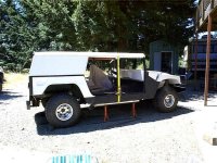
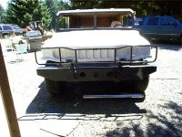
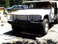
Here are a couple pics of a wild AZZ idea I had a few years ago...
A hummer kit.....
GAWD...WHAT A JOB
The kit came with the Steel tub, the fiberglass top, steel door frames and fiberglass skins. Fiberglass dash.
Tons left to the imagination...
The Grille guard is an OEM H1 hummer part.
Mount on a chevy Suburban 4x4 (Used a 1987 1/2 ton Burb 4x4 with a 6.2 diesel.
Instructions were crap...I just did my thing.
Got it finished and a guy with a lot of $$$$$ came along and had to have it......So it went away...
Attachments
Snowy Rivers
Well-known member
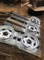
Grabbed a couple cans of "Cowboy Chrome" paint this morning....Cleaned up the 4 Snowflake wheels that are all welded and gave them a shot of paint.
Spoke with a shop up in Portland earlier about filling the tires with Urethane tire fill....
We discussed what was needed...I grabbed the tubeless valve stems while were were in town....
Installed them with some soap after the paint dried.
Going to mount the tires and air them up...Once the cat is ready to go....then fill them up.
I ordered up a pair of 10 ply 145/r12 tires this morning too....These are very very close to the 5.30 x 12 bias ply....
We shall see how they work.
10 ply and when filled they should work fine......
I do not want to run any air filled tires...
All spots except the front two on my cat were tubed and air filled.
Wheels beat all to hell after a tires lose air....Tire guides just eat them suckers.
So today has to be a good solid 9.....10 is an unobtainium spot.....at least here....
I think I may mix in a pair of the bias ply tires and see how they hold up.
10 ply seems to be tough to find....8 ply is the norm.
I am not getting suckered into spending huge $$$$$$ on Falline or Alpine guide.
That is what was on this machine.....They were torn up pretty good too.....
A couple that were not torn up were just checked badly from years in the elements...Not worth the trouble to try and salvage....just too rough....
I can't get any tire guys that know anything about why the "Snowcat Special" is soooooooooo good.
My local tire guy has been in bizz here locally forever and his father before him.
The old man is in his late 80's and we have discussed this topic.....He just smiles and rubs his fingers ....Gesturing $$$$$$ in somebodies pocket....
Solid urethane would be sweet.....$$$$$$$$$$$$$$$$$$$$$$$$$$......
This cat is gonna get whatever 10 ply tires I can scare up and then fill them....
Will see what shows up here in a few days......