• Please be sure to read the rules and adhere to them. Some banned members have complained that they are not spammers. But they spammed us. Some even tried to redirect our members to other forums. Duh. Be smart. Read the rules and adhere to them and we will all get along just fine. Cheers. :beer: Link to the rules: https://www.forumsforums.com/threads/forum-rules-info.2974/

Need 1644 or 1544 cab demensions

Looking for someone that has a 1644, (or 1544) that would be willing to help me out with some pictures of the interior of their cab (and possibly some measurements?)

I'm in the process of converting my 1642 into a 1644, and all I have to go by is a handful of pictures of 1644s from a distance.
I know I can make it work with the info I have, but would love to get some more information on a few details from a factory design if someone was willing to help me with that.

We can post directly to the Forum or if phone numbers are easier to exchange texts that's fine with me.
 
What measurements do you need?
Looking for the total length of the cab, or really just where the rear of the cab ends.
It appears it'll be just after if the upper frame support above the rear track. Maybe a measurements in relation to that?

Also, More importantly, I can't tell how much room they allowd behind each door.
Currently, on my 1642 I have 9.75 inches from the where the door Striker is to the cab corner. I have to cut that section out and I can't tell how much Tucker allowed on the 1644 models. Currently there is only a .75" Square Tubing that runs vertically just behind the doors and goes up to the roof. Then the 1.75" square tubing that is the main roof support is just next to the rear window on the back wall. I believe I want to replace the .75 square tubing behind the doors with 1.75 inch square tubing just behind the front doors as well as just behind the rear doors to give correct roof support and roll over protection. ( Hopefully not needed 🫣)
The relationship between the rear door hinges and the front door might be nice to have as well. And then I would assume Tucker originally allowed for the same amount of room behind the rear door is what he did behind the front door, but I'm not certain of this.

When I say room behind the door, specifically the point from where the front door strike would hit to the opening for the rear door, and from there where the rear door strike is to the cob corner.

I'm scrolling through threads, yours included, looking for pictures of how the interior of those cabs were framed from the roof, walls, floor, and back wall.
 
I printed out your response and I'll take that with me to get measurements. However, the only four door cab I have to measure is a 1980 Tucker that became the Thundercat project.

That cab had significant rust, both the steel sheet metal panels, and a number of the cab frame members. Almost all the cab frame members were replaced, as were the kick panels, the panels between the front and rear doors, and the rear cab panel. We also changed the design of some of the frame members, as well as the dimensions of some of the tubes. The measurements will be very close to factory, but may be slightly different.

Here are some pics.

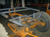
This is the factory rear cab frame. There is an arched part that supports the roof, and we cut that off and reused it.

My recollection is the bottom of the rear frame was welded on top of the longitudinal truss frame members.

DSC01597.JPG


This is what we replaced that with and you can see we welded the lower horizontal frame member between the longitudinal frame members and we put the vertical members in the corners on top of the longitudinal frame members. We also used 2" steel tube as opposed to 1.75" tube, and it was a thicker wall thickness. Note also the diagonal braces. The change in both materials and design was for greater strength and rigidity as compared to the factory design. Note how all those frame members converge and are then tied into the lower truss frame.

DSC01645.JPG


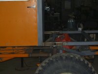
All eight door posts are new, new center center cab roof support and "roll bar", all new rear cab framework and all the upper longitudinal cab frame members are new, as well. (The furthest aft door posts have not been installed yet.)

DSC01629.JPG


This is a pic of the center cab framework and roof support.

DSC01651.JPG


Here's that rear arched roof support I mentioned above

DSC01648.JPG


Every project I've ever done has had some aspects that in retrospect I wish I had done differently. Scott and I are in total agreement we wish we had made the cab bigger. By bigger, I'm saying longer, wider and higher. Longer is the easiest of the three, and I would highly encourage you to consider this. Seat choice is certainly a factor, but there is precious little rear legroom in Thundercat. If I were doing another one, I would make the rear cab 6" longer.

To do that you'd have to have a shorter bed or stretch the frame. The factory bed on this machine was kind of pathetic. It was 6' wide and 4' long. Except the gas tank was 4' long and 1" wide. Of course it's mounted transversely, but that renders the usable bed space only 6' wide and a measly 3' long. We decided to make a significantly bigger bed and stretched the frame 12".

Just because Tucker did it a certain way doesn't mean you have to. You have a blank canvas, and can build the cab any way you like, and believe me, there is very definitely room for improvement.

Please give some thought to making it the way YOU want, and then take your time in considering options and dimensions. I genuinely believe it will be time well spent.

I'll get you the measurements ASAP.
 

Attachments

  • PICT0547.JPG
    PICT0547.JPG
    171.8 KB · Views: 21
  • PICT0552.JPG
    PICT0552.JPG
    174.1 KB · Views: 18
  • PICT0556.JPG
    PICT0556.JPG
    110.6 KB · Views: 20
Dimensions:

Measurements are from what I'll call the "firewall flange". This is the part of the cowl that is bent at a 90º angle to overlap the firewall.

I'll label the four door posts as A, B, C, & D from front to back.

Firewall flange to rear cab corner, essentially the overall length: 89.5"

Firewall flange to rear of A post: 10.25"

Firewall flange to front of B post: 46.625"

Firewall flange to rear of C post: 49.75"

Firewall Flange to front of D post: 86.3125"

The center door post area, the difference between the B and C posts, is only 3.125". You asked about the location of the rear door hinges, but I wouldn't blindly weld the hinges in that location and hope the door fits. I would set the door in position with (shims and clamps) and with the hinges attached to the door. Then open the other end of the hinges so they are flat against the center panel and tack weld them in position. Remove the clamps and shims and check rear door operation. If satisfactory weld the hinges in position, if not, cut the tacks, and do it over again.

In a perfect world, everything lines up. In reality, you're working with a 40 plus year old vehicle built by a company with somewhat loose manufacturing tolerances.

Having "been there and done that" I highly recommend you check your truss frame members for straightness before you start cutting and welding new cab frame members. I strongly suspect your frame will be bent. In that case you should straighten the frame, or cut out and replace the bent sections.

On the 1544 project we cut the outer truss frame members just behind the C post on both sides, and replaced them and the rear frame crossmember that connects the two. This is a 1986 Tucker and they had made some changes to the frame, but it is illustrative of the repair process.

Pics:

IMG_2677.JPG


IMG_2674.JPG


IMG_2688.JPG


IMG_2680.JPG
 
Dimensions:

Measurements are from what I'll call the "firewall flange". This is the part of the cowl that is bent at a 90º angle to overlap the firewall.

I'll label the four door posts as A, B, C, & D from front to back.

Firewall flange to rear cab corner, essentially the overall length: 89.5"

Firewall flange to rear of A post: 10.25"

Firewall flange to front of B post: 46.625"

Firewall flange to rear of C post: 49.75"

Firewall Flange to front of D post: 86.3125"

The center door post area, the difference between the B and C posts, is only 3.125". You asked about the location of the rear door hinges, but I wouldn't blindly weld the hinges in that location and hope the door fits. I would set the door in position with (shims and clamps) and with the hinges attached to the door. Then open the other end of the hinges so they are flat against the center panel and tack weld them in position. Remove the clamps and shims and check rear door operation. If satisfactory weld the hinges in position, if not, cut the tacks, and do it over again.

In a perfect world, everything lines up. In reality, you're working with a 40 plus year old vehicle built by a company with somewhat loose manufacturing tolerances.

Having "been there and done that" I highly recommend you check your truss frame members for straightness before you start cutting and welding new cab frame members. I strongly suspect your frame will be bent. In that case you should straighten the frame, or cut out and replace the bent sections.

On the 1544 project we cut the outer truss frame members just behind the C post on both sides, and replaced them and the rear frame crossmember that connects the two. This is a 1986 Tucker and they had made some changes to the frame, but it is illustrative of the repair process.

Pics:

View attachment 190129

View attachment 190130

View attachment 190131

View attachment 190132
Thanks so much for all this!! I really appreciate the time you took to measurements, record and type such a well explained reply. It is very helpful. That is exactly what I wanted to know. Also, some very useful pointers and tips as well. I'm sure I will have more questions as the project continues.

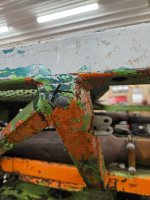
Actually, here is another question. Have you ever looked or thought about a way to install any sort of rubber body mounts between the frame and body/cab. Obviously the brand new Tuckers are a completely different design, but they have Incorporated air ride cab mounts. That's probably very unrealistic with this era tucker, but even rubber body mounts would cut down on cab vibration significantly. There is so mucb driveline vibration that goes to the cab and makes everything rattle/vibrate, ect. On my Tucker essentially everything is metal to metal, with no rubber cushion between the engine mounts, transmission mounts, exhaust mounts, or body since the body is well directly within the frame. I know this would not be an easy task, but I was considering cutting the vertical posts that extend from a lower part of the frame the upper part of the frame and installing rubber body mounts between each one of those. That would give a significant amount of cushion and cut down on drivetrain vibration between the cab and the frame. Wondering if you had ever thought anything about this? I don't know how much structural Integrity would be lost if the upper outer part of the frame wasn't directly connected to the lower inner part of the frame. If I had do, I could run a second horizontal part of the frame below where the body mounts would be for extra structure. It may not be worth it at all, just wondering what your thoughts are.

Also, From what I can tell comma my roof And my door panels are aluminum, with everything else being Steel. I will have to make a new roof, and making the rear doors. Do you think it would be wise to keep the roof and door panels aluminum? I'm sure it is partly for weight as well as corrosion, but not sure if it's worth keeping the new panels aluminum.

(I attached a picture with an "x" where I was considering cutting and installing body mounts all around)
 

Attachments

  • 20250407_182246.jpg
    20250407_182246.jpg
    2.2 MB · Views: 25
Top