• Please be sure to read the rules and adhere to them. Some banned members have complained that they are not spammers. But they spammed us. Some even tried to redirect our members to other forums. Duh. Be smart. Read the rules and adhere to them and we will all get along just fine. Cheers. :beer: Link to the rules: https://www.forumsforums.com/threads/forum-rules-info.2974/

Astro van cat conversion

olympicorange

Active member
……. S/R,.. looks like your ''stinger'' worked well and did the job. here's a pic of one of the ones I use,..this one is on the front of a JD6310. as far as all the holes in the ''tub'' ,... the easiest thing to do is fill them with hardware,... and if you mix it up, with different sizes and lengths,... if you need any out in the ''sticks'' , you'll have them with you,....otherwise just counterweights,....:smile:
 

Attachments

  • 0420201037_Film2.jpg
    0420201037_Film2.jpg
    116.1 KB · Views: 188

Snowy Rivers

Well-known member
Yessssss..Gotta make the equipment gitterdone... attachments are the real deal.


The top hat is my parts washing pot (Stainless Jello bowl)
Great for doing bearings and stuff as it never rusts.

I grabbed it to keep the Carb stud for poking a hole in the tarp....
Rain is still in the the forecast and I do not want my prize full of water.

The little 305 may not be the prettiest girl at the ball....but at least it will make things go.

Before I stuff it in for good I want to steam clean it off and get it a tad nicer looking.

From what I can see the package is usable...at least for the time being.

Trans oil is PINK...GOOD SIGN :clap:

Future plans include tearing both the engine and trans apart and going through them.

Heads have been off the engine (Different color) so likely either somebody replaced them for for zip in the mini mouse...or there may have been an issue...

Doing a "TAILGATE" overhaul is likely...Rings, bearings, seals and such.....

Nothing crazy....just a freshen up.

Trans would include seals, clutches, upgraded sprags/roller clutch a shift kit....maybe a few other goodies depending on what I find after opening up the box.

As far as a single seater ?????? probably not :smile:

I am a old fart....gotta have creature comforts ya know.:thumbup:
 

Snowy Rivers

Well-known member
Got out the S10 EXTREME drive line and tossed it in the cat.

A bit too long....I had hoped it could fit in stock length...but shortening the short single joint section is easy.

Gonna wait until the engine is fully mounted and the diffy is repaired and back in to cut the shaft.

The overall package is looking good.

Got out the magnetic protractor and got some readings

Diffy pinion is at 90 degrees as is the tub
The engine is at 88 degrees

Need to lift the rear of the trans a bit to get us spot on.

The new rear mount will be here Thursday says the tracking ###

Got the front mounts marked for drilling, but will wait until I see wassssup with the rear mount before yanking the engine back out again.

I really don't think I could ask for a better first fitting than this has gone.

After the rear mount is cut to fit and things are checked for final position the mounts end flange units can be welded onto the cradle tubes.....

Just like Legos.....
 

Attachments

  • IMG_2557.jpg
    IMG_2557.jpg
    538.2 KB · Views: 165
  • IMG_2558.jpg
    IMG_2558.jpg
    444.6 KB · Views: 164
  • IMG_2559.jpg
    IMG_2559.jpg
    464.8 KB · Views: 161
  • IMG_2560.jpg
    IMG_2560.jpg
    318 KB · Views: 166
  • IMG_2561.jpg
    IMG_2561.jpg
    230 KB · Views: 177
  • IMG_2562.jpg
    IMG_2562.jpg
    357.5 KB · Views: 163

PJL

Well-known member
Okay, it's late and I'm tired so I hope this isn't a dumb question. Doesn't the driveshaft need a carrier bearing in the middle?
 

Snowy Rivers

Well-known member
Certainly not a dumb question...not at all.. :smile:


Short answer...Yes it does

Long answer

When I bought the shaft back this winter I got it from a drive line shop in Tacoma and they had to scrape together the pieces.

The rear section (The double double) was in the Tacoma shop and the short singe cardan section was at the Seattle shop.

They shot me a price on the pair AS IS and shipped them down to me.

The carrier bearing was not on the shaft as it had been cleaned and put on the used shelf for sale or ???

I am waiting on buying the bearing until I get good data on which type will best suit whats needed in this application.

As soon as I get the rear mount and get the power pack located with bolts and not just blocked up with wood....then I will look at the situation and make a decision on which bearing type to get (Several styles available)

CARRIER BEARING COMING SOON TO A CAT NEAR HERE..:smile::smile:

Actually...when I tossed the shaft in the tub I was primarily interested in where things were as far as the length of the shaft was concerned and if I had any serious issues AS IN TOO SHORT OR WAAAAAAAAAY TOO LONG...so it was just a Quick..lets see what this looks like before we get too far down the road.....
 
Last edited:

Snowy Rivers

Well-known member
Spent time looking for the proper yoke to slip into the transmission.

The Driveshaft has all Saginaw 3R series u joints.....I did not want to mix and match on the u joints....

The prices on a new 3R yoke to mate with my existing short shaft were a tad bit past what I was willing to cough up....

Headed to the local U pull it yard and we cruised down to the Astro van lineup...

Right off we hit on a 1992 ASTRO with a factory original type front yoke.

Still had the injected plastic retainer on the u joint :thumbup:

The shaft had been munged a bit by the large forklift when they set the van in the yard.....No worries....I only wanted the nice yoke with the vibration damper.

$49 for the shaft and 15 minutes to slide under and unbolt it....

Got it home and in the vice...hit the yoke with the torch and melted the plastic out....these bad boys can squirt hot plastic and one needs to be aware of what can happen.

Much easier the beating them out or breaking the plastic in the press.

Distorting the yoke ears can happen if one gets too rough with things...

Sweet little yoke.

Once the shaft is complete I think a trip to the balance shop would be well worthwhile....

Getting the entire shaft assembly balanced will make a very smooth running drive train.....


Very pleased to find the exact yoke I wanted right off....we got back to the yard office and the sky opened up and it poured for an hour....

We were lucky not to have gotten soaked.....


Another piece of the puzzle taken care of......

Rain is still in the forecast over the next few days....Once the rain ends and I can get back onto things the front mount holes in the body need to be drilled.

And onward we go....

Sooooooo much fun.
 

Attachments

  • YOKE1.jpg
    YOKE1.jpg
    415.4 KB · Views: 133
  • YOKE2.jpg
    YOKE2.jpg
    559.9 KB · Views: 127
  • YOKE3.jpg
    YOKE3.jpg
    157.6 KB · Views: 131

Snowy Rivers

Well-known member
Got some good dimensions around the front of the engine down low on the left side...
GREAT PLACE TO MOUNT THE YORK COMPRESSOR to handle the air needs for steering.

Then the realization that the Vans use a hydroboost brake booster (Plan is to reroute the front brake lines back to the rear outboard disc brakes by the sprockets.

Disc brakes generally will not work well without power assist....

Always something that needs to be sorted out.

I had no intent of having any hydraulics on this cat.

The steering box will be basically useless other than allowing the van to be rolled onto the cat chassis.

But I had forgot about the brake thing.

Arrrrrrrrrgh

Well...decided to try rolling the van down the hill with the engine off and the hydrobooster accumulator exhausted (Manual brakes) Ahhhhh...bad plan..ya really got to have your heart in your work on that one.

GM did not use a vacuum booster on these because of the space needed in the area in front of the cowl.

I want to keep the factory brake system intact and just connect new lines at the front wheel house location where the soft lines connect.

There are aftermarket dual diaphragm vacuum boosters that are 7" in diameter and they are very affordable.

There looks to be plenty of room in the area of the master cyl/hydrobooster to get one in....

These units will not provide as much assist as what the DOT requires for stopping the van...But the cat is not gonna be rolling at 80 mph down the hwy either and the small vac booster should be perfect.

The other issue is these boosters require a fair amount of vacuum Inches-Hg

I plan to stuff a bit of a lumpy cam in the 305 soooooooooooooooooo...may need to bolt on a vacuum pump off a 6.5 GM diesel to assist in the SUCK....

Gotta save the room for the air pump down below...

Another issue sorted out.....:thumbup:
 

PJL

Well-known member
I'm wondering how badly you really need the extra disc brakes. The LMC1200 uses the OC-12, it weighs a tad under 8,000 lbs. It stops just fine using the steering brakes. It has no foot brake. The brake off the back of the transmission is for parking only.
 

Snowy Rivers

Well-known member
Under normal circumstances I would agree 100%
With the air system I am setting up on the OC12 there is really no easy way to feather the pressure to the air brake cans.

The steering bands are on or off.

The Spryte controls with the hand levers actuating the indididual master cylinders will allow for light pressure right up to full pressure.

The 2100 had hydraulics run off the main hydraulic system and they were/are pretty much on and off.

My second reason is that having the outboard disc brakes as a separate system will allow the same sort of brake control as is available in a truck or SUV ??????

If the air system should have a failure there would be a very easy safe way to stop and control the cat.

Snowcatcrazy added the outboard disc brakes to his big van/cat 2100

Seems that they had an issue coming off the Mt and things got real hinky and damned near put the cat off a cliff...

After that fiasco he installed the rear disc brakes.....

Installing a pressure regulated valve system to the bands gets more entailed and trying to pack all the controls into the drivers area of the Van will get quite cumbersome..

I have thought of using to treadle type valves with handle to control them.

Sadly the little Astro has so little room to add much ion the driver area.

Even the full size van is somewhat limited for room as well..

I built the attachment that fastens to the steering wheel to control the air to the bands....but the valves are on/off type and feed off a master pressure regulator that feeds the system.

Before we get to that part I may explore things a bit more and see what can be done.

There has been change orders already....why not make other changes :thumbup:

NOTHING IS CHISELED IN STONE ON A Frankencat.....
 

Snowy Rivers

Well-known member
There is a valve that could be used IF there is enough room to install two of them on the steering wheel control bracket assrmbly

These are air brake truck trailer brake control valves.

Two of these would allow pressure to be varied from Zero up through a maximum of whatever is deemed MAX pressure for the bands.


As I said...change orders are always in the pipeline.

Air from the tank to the hand valves...then to the relay valves for each air chamber.

When X is applied by the hand valve the relay valve will apply X to the chamber.

This would allow a light pressure on the band all the way up to hard locking.

I'm going to need to look at one of these valves and see how much space they take up....

If two of these can be mounted on the operator station I have built that sits on the wheel....we might be golden.

Certainly could save a lot of extra work and materials.....for sure
 

Attachments

  • Screenshot from 2020-04-23 15:45:55.jpg
    Screenshot from 2020-04-23 15:45:55.jpg
    53.3 KB · Views: 100

loggah

Active member
SUPER Site Supporter
My big oliver- cletrac FDE model has air steering assist you can steer it with 2 fingers. this differential is the same as a oc-12 only bigger,oc-18 I think Landis zimmerman cletrac has the steering vaves. but there probably pricy!!! Heres a picture of the tractor,and at work when it was hauling pulp for great northern paper up in Maine.Don

original.jpg


original.jpg
 

Snowy Rivers

Well-known member
Thank you for posting the cool pictures.

We had an HG Cletrac here at the ranch for many years....The little HG was a baby compared to the Big brute in the pics.

There are many valves available that can be used to run the air steering, but the big issue is size...

Trying to keep the valves in a size range that will fit in the operators area is a tough one.

I am glad to see others offering ideas and asking questions....this may end up helping find a really cool solution.....
 

Snowy Rivers

Well-known member
Weather is making things a tad nasty outside...

The rear trans mount came last night.

Got that bad boy out of the box and trimmed to length.

The overall location of the engine and trans are really close to the factory setting.

Got the trans mount bolted to the trans.... GAWD...WHAT A PAIN WITH THE TRANS CLOSE TO THE TUB.

It is doable, but it takes a bit of finesse to get the bolts in.

Once the mount end caps are all bolted up with the spacers between the end caps of the mounts then the tube gets welded to the end caps.

Finished getting the front mount spot on and then used a transfer punch to locate the top holes in each side.

Next step is to remove the power pack and drill the holes in the tub.

I have some 1/4" x 6" x 10" flat steel to go between the mount ends and the tub......The shim

The old engine mount bolt holes will get used to secure the shims as well as the new holes too....

Tedious work getting the engine spot on as far as straight with the tub C/L

A touch here, a bump there and a clamp here or there to keep things from moving.

A few pics

One nice thing...the mechanical fuel pump is a breeze to get to on this beast.

Thinking about the fuel system as bit.....

Likely will cut an access port in the floor of the van to be able to access the fuel Pump/gauge sender in the tank....

Modify the unit to swap out the high pressure pump and maintain a simple pickup tube.

Will add an electric low pressure pump to be able to prime the mechanical pump if need be.

The easy access up front and some lovely places to mount the electric pump and a nice filter.

The oil filter on the little Chevy mouse is a pain to get to.... A remote filter up front will be an easy fix for that issue as well.

An oil pan drain extension hose like those used on boats will get the drain out to the front of the cat as well.

So many things to deal with that present themselves as time goes by.

I am thinking about a deep pan with an extended pickup tube for the trans...

Anyway....
Moving ahead...
 

Attachments

  • REAR MOUNT1.jpg
    REAR MOUNT1.jpg
    474 KB · Views: 178
  • REAR MOUNT2.jpg
    REAR MOUNT2.jpg
    450.6 KB · Views: 179
  • FUEL PUMP ACCESS.jpg
    FUEL PUMP ACCESS.jpg
    331 KB · Views: 178

olympicorange

Active member
There is a valve that could be used IF there is enough room to install two of them on the steering wheel control bracket assrmbly

These are air brake truck trailer brake control valves.

Two of these would allow pressure to be varied from Zero up through a maximum of whatever is deemed MAX pressure for the bands.


As I said...change orders are always in the pipeline.

Air from the tank to the hand valves...then to the relay valves for each air chamber.

When X is applied by the hand valve the relay valve will apply X to the chamber.

This would allow a light pressure on the band all the way up to hard locking.

I'm going to need to look at one of these valves and see how much space they take up....

If two of these can be mounted on the operator station I have built that sits on the wheel....we might be golden.

Certainly could save a lot of extra work and materials.....for sure

,...…. these are generally referred to as the ..''trolley'' valves. you can apply a lite amount of air pressure,...or wide open ,...up to 120 psi. spring loaded hand control, back to neutral. also , in an ''over the road'' truck ,... a lot of rigs have an ''applied '' brake pressure air gauge on the dash, to inform the operator on how much air assist pressure is being delivered,... easy enough to plumb a pair in also,....:smile:
 

Snowy Rivers

Well-known member
Oly orange

Yes....I spent over 20 years in a big rig and about 2 million miles

That is what sparked the idea of maybe using the"Trolley valve"

My one worry is the possibility of someone dragging the brake bands.

I learned to drive a crawler on a little Cletrac HG same rear box as the C4 used in some Sprytes

Owned and operated this beast from 1995 to 2012
Retired in 2012

That rig had the trolley valve....I ordered the truck with it as some don't come with them.

That rig had every goody and gizmo I could get on it.
500HP Cat 3406E
18 spd Fuller
2 speed 46000 pound tandems with air lockers.
Heavy duty frame.....
We ran 105,500 gross weight all the time....paid a lot better than standard 80K

No stranger to rigs with air
 

Attachments

  • WSTFR2.jpg
    WSTFR2.jpg
    24.8 KB · Views: 155

Snowy Rivers

Well-known member
OMG
Life is great.
Fella called on the Craig's ad for the Camaro sub frame
He left about 30 minutes ago...

He was happy as a clam and I have my engine and trans free and money in my pocket over and above the original cost.

He did not want the core support...so now that's listed back on Craig's list..

Gawd I love getting to use my $$$$$ more than once.....:clap:

Time to do more cat things...:smile::smile:
 

Jim_S

Gone But Not Forgotten
GOLD Site Supporter
He was happy as a clam and I have my engine and trans free and money in my pocket over and above the original cost.

That’s the way it’s supposed to be! Both parties to the deal happy!
 

Snowy Rivers

Well-known member
Yes indeed.

The sub frame was really clean...as far as rust goes.

Needed a good blast with the hot washer to get 40 plus years of greasy crud off....but the paint is still on the frame.

Had everything else including the pwr steering box and sway bar, disc calipers and good rotors too.

A great deal for us both.....best part is I don't have to look at it sitting in the yard with the rest of the scrap iron from various projects....

And of course the sweet little 305 and the TH350 sitting in my cat is the icing on the cake.....

Guy did not want the core support and the bumper attaching hardware....more booty $$$$....maybe pay for a new carb or some goodies for the cat....

Now if I can find someone who wants a 2100 tilt cab to take home and love....life would be real sweet.
 

Snowy Rivers

Well-known member
Extra cat parts pictures
 

Attachments

  • IMG_2579.jpg
    IMG_2579.jpg
    575.3 KB · Views: 162
  • IMG_2580.jpg
    IMG_2580.jpg
    618.5 KB · Views: 155
  • IMG_2581.jpg
    IMG_2581.jpg
    594.2 KB · Views: 164
  • IMG_2599.jpg
    IMG_2599.jpg
    534.1 KB · Views: 149
  • IMG_2600.jpg
    IMG_2600.jpg
    612.2 KB · Views: 154
  • IMG_2601.jpg
    IMG_2601.jpg
    523.3 KB · Views: 144
  • IMG_2602.JPG
    IMG_2602.JPG
    519.9 KB · Views: 156

loggah

Active member
SUPER Site Supporter
Looks to be a valley engineering blade setup made in Grey,Maine. Do you have the hydraulic steering actuaters that bolt to the seat? i could be interested in them for spares if you want to get rid of them.thanks Don
 

Snowy Rivers

Well-known member
Don
At present I have an interested party in the cab and other stuff.

Lets see how this progresses.

The actuators are still in the cab....
 

Snowy Rivers

Well-known member
Had a very productive day today.

Lifted the engine back out and went to work on making the 1/4" shim to utilize all the extra bolt holes right around the motor mount.

The blade lower mount had a bracket that bolted onto both sides of the lower tub...
Several holes left after the brackets come off.

The RH bracket is still on the rig....the last crew did a bit of welding on it...
Looked as though it had been wiggling and they welded part of it to the tub.

Gotta cut about 6 inches of weld off.....

A nice hole behind the bracket that will be sweet to remove the starter if need be..

Did the layout of the shim plates and was able to use a transfer punch to locate the holes from the tub onto the plates..

12 bolts on each plate.
The original 4 mount bolts, the 4 new ones and 4 left overs from the blade lift bracket.

A lot of holes in the old Packer for sure.

After getting the shim plates drilled and bolted in (My supply of bolts has left me.....I need to get a bunch of 3/8" x 1 inch bolts.

The new mounts came with bolts, but they are 1-1/2" long.....too long

At final assembly I will use lock nuts on these bolts to keep the stuff from rattling loose.

After getting the mounts secure and the engine sitting free of the lift the angle of the crank shaft is spot on...

The protractor shows a nice 90 degree reading.

So now the crank is parallel to the OC12....Sweeeeeeeeeeeet..

Front mount is welded to the end plates....will need a bit more before it's all done....I did 3 good tack welds to secure things

The next order of business is to cut the shim plates for the rear mount and transfer the bolt holes from the old rear mount and also transfer the ones from the new mount.

The trans is sitting on 2 x 4 under the pan....things are perfect.

I want to replace the pan with a 3" deep aluminum pan with a extended filter..

Get a bit more oil volume and allow for a bit more operating angle too..


Weather closing in again....not sure whats in store as far as getting much work done this coming week....we shall see.
 

Attachments

  • Front mount final trial1.jpg
    Front mount final trial1.jpg
    264 KB · Views: 170
  • Front mount final trial2.jpg
    Front mount final trial2.jpg
    401.2 KB · Views: 164
  • Front mount final trial3.jpg
    Front mount final trial3.jpg
    346.4 KB · Views: 181
  • Front mount final trial4.jpg
    Front mount final trial4.jpg
    406.1 KB · Views: 184
  • Rear mount ready to bolt up2.jpg
    Rear mount ready to bolt up2.jpg
    454.8 KB · Views: 168
  • Rer mount ready to bolt up1.jpg
    Rer mount ready to bolt up1.jpg
    255.5 KB · Views: 170

Snowy Rivers

Well-known member
After thinking about the post OLY ORANGE made concerning the "Trolley valve"

My years of experience in a big rig had always had a trolley valve as a fairly large valve that mounted on the steering column RH side.

These valves are pretty good size and I had dismissed them early on in the design phase of getting an air steering system put together simply because of the size.

After Oly mentioned it recently I decided to revisit the idea and started cruising the Web looking at various trolley valve pictures.

BINGO.

Freightliner panel mounted valves popped up.

Decided to dig deeper and these bad boys looked like a perfect fit for the job.

A slight modification to the steering wheel mounted control panel and two of these valve can mount in nicely.

Pushlock hose fittings that accept the 3/8" and 1/4" nylon DOT brake lines

Sweeeeet

The valve is designed such that it has a spring return to ZERO and the layout will suit this application well.

Another plus....Off the shelf item that's available easily (Napa heavy parts or just about any truck supply house....

Found two of these on ebay $50 for the pair.

Will give these a good looking over and get the control station modified.

These valves will greatly simplify the air system....

A regulator that will keep the air pressure at no more than what the bands need to lock up tight mounted at the tank....and a relay valve near the OC12..Simple yet very affective...

I like it......

Thanks Oly Orange for mentioning this subject.......:thumbup:
 

Attachments

  • Brake valve.jpg
    Brake valve.jpg
    129.1 KB · Views: 130

PJL

Well-known member
Nice, like Loggah's tractor you can drive it with your fingertips. Pulling both will stop the cat. If you can rig up a driveline brake that would be pretty effective as an emergency/parking brake.
 

vintagebike

Well-known member
While driving a Tucker Torpedo with skis on the front at Jug Mountain a few years ago it was difficult to turn on the tight trails. So when redoing 1949 Sophie we replaced the rear axle with a disc brake unit from an 1998 S10 Tahoe SUV but removed the anti-slip parts. Each side uses its own vertical pull back drift brake lever mounted on the transmission with one electric actuator for both parking brakes. Should turn and stop on a dime.
 

Snowy Rivers

Well-known member
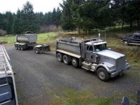
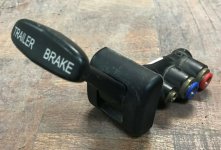
Yeah buddy....FINGERTIP CONTROLS :thumbup:

Still thinking about using the rear disc brakes though.

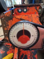
I like the idea of a separate system that applies full and varied brakes.

In the event of an inexperienced operator in command, the natural tendency in a sketchy situation is going to be...STEP ON THE BRAKE PEDAL

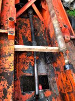
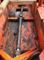
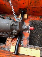
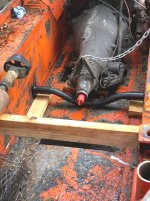
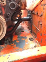
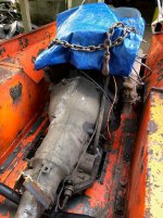
The vans brake system will still be fully functional and just lengthening the hydraulic lines and a little bit of work will get the system fully operational as a backup.

Unplug the ABS unit and remove the lamp in the dash.

This sucker will be annoying as it will not see signals from the output shaft sensor or the wheel sensors.

Unplugging the ABS will allow the brake system to function just fine to do whats needed.

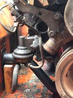
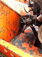
The trans park lock will still be usable as well.

With the low gears in the butt end there will not be much tension on the park pawl.

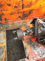
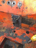
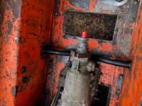
Using the trolley valves will really simplify the hose s needed to the operator station as well.

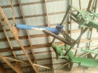
Black line...Supply air
Blue line...Left side relay valve and air chamber
Yellow line...Right side relay valve and air chamber
Two 1/4" lines from the hand valves (Exhaust out to the engine bay)

Far simpler set up than I had before...

Also the trolley valve will allow for a gentle nudge on the steering to correct a slight direction change instead of a full on application.

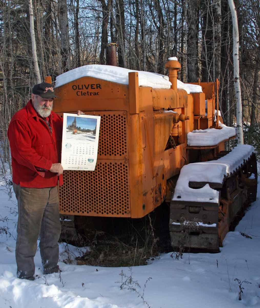
Our old Cletrac used the C4 box and a slight nudge on the hand lever would give a little correction....

Anyway....I am very excited about this change order.....

Be nice to get rid of the lettering TRAILER BRAKE on the handles.....ah well
Maybe fill in the letters with JB weld and paint the handles black.....

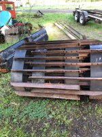
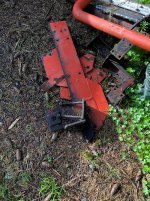
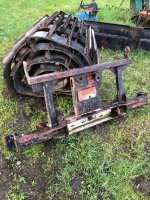
Franken cat thing ya know..... Reminds me of the Johnny Cash song about his buddies car "One piece at a time"
 

Snowy Rivers

Well-known member
Vintage bike

Most definitely will work sweet.

"Cutting brakes"
I had a similar thing on a sand buggy.

Two levers to independently activate the wheel needed to be able to steer when climbing steep dunes when the wheels up front were off the sand or ????

Oh yess
 

Snowy Rivers

Well-known member
Got to work on things and discovered that the engine placement had somehow slipped to the LH side by about 3/16"

A bit of snooping revealed that the engine cradle tube was a touch long on the right side and when I pushed the engine over with a small jack just before tack welding the mount ends the RH side of the tub had flexed a bit.

3/16" is not much....but I was not going to let that slide.

Decided to lift the power pack out, remove the front mount assembly and FIX the anomaly.

Got the cradle back out, cut the tack welds loose and cleaned up the two end pieces.

Sure enough...the RH end of the cradle tube was hard against the inside of the end bracket (Weld to the cradle tube at assembly)

No room to allow the engine to slide over freely......

I cut about 1/4" + off the end of the cradle tube and reassembled the mount.

Dropped the power pack back into the cat, bolted things up and aligned the engine.

Spot on this time with the engine sitting on the mounts freely.

Tacked the mound ends back onto the saddle tube....


ALL GOOD TO GO NOW

Now its time to get the rear mount shim plates cut and the new holes drilled.

Cut the RH lower blade bracket off of the tub....The last crew had welded it partially to the tub..... real mess....Looked like a flock of seagulls few by and Chit.


And a good time was had by all....:clap:
 
Top