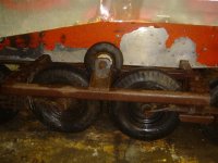
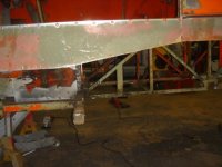
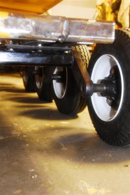
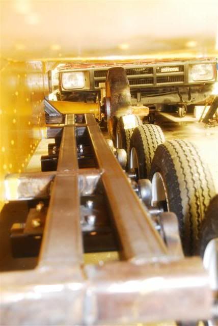
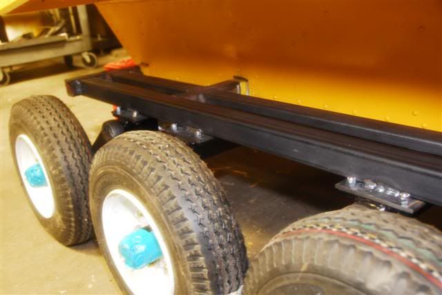
Since I cut the original suspension tubing back to fit the torsion axle frame and wanted to replace the original 8" broken solid front idlers with two 16" tires I already had, ended up making a different adjuster compensating for the difference in height.
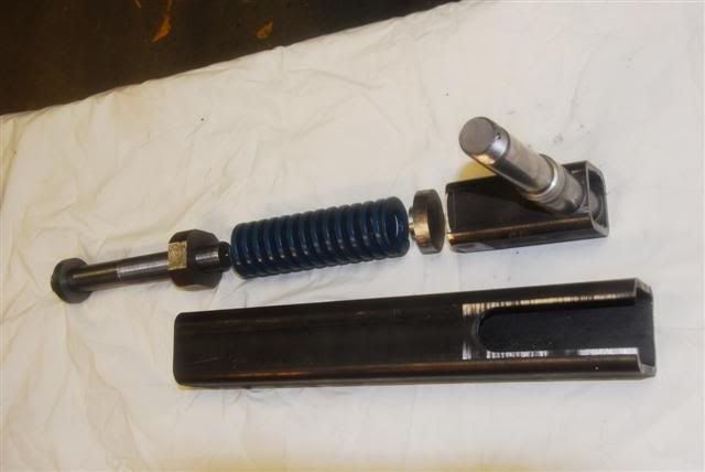
Maybe overkill for the Imp but was fun trying to make it all fit and work together. It has 4 inches of fine adjustment with the bolt and the original coarse adjustment plate (not shown) gives it a additional 3" or 4", should be plenty. I don't have a picture of it all together, have to get one later with the wheel mounted. Grease zerks are fitted so the whole unit is easily lubed. The 1" adjustment bolt is machined with the same bolt head as the lug nuts and threaded 12tpi out of 4140.
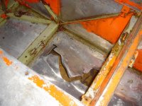
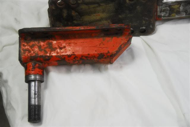
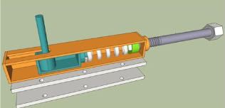
Altered it from this original drawing some. The adjustment bolt now runs inside the spring with a sliding nut. The adjustment bolt is captive at the end, Just the bolt head and a lock collar stick out. The nut slides inside the 2.5" tubing compressing the spring.
The spring is suppose to take out some of the shock of hitting something? Really, I just thought it was cool to have a spring?
Had a time trying to figure out a spring rate that would work well on this, ended up using a medium die spring rated around 1100# at full compression, the spindle is only rated at 1250#. The spring fits nicely inside the 2.5" tubing with very little play, had to remove the welding flash from inside to get the spring and the smaller tubing to nest.
Bobby


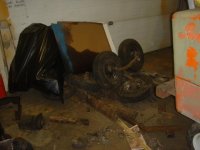
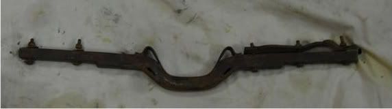
 , That rack was really nice and sturdy, You could walk around on it. Unfortunately it was heavy i'd guess over 400lbs, all two guys could do to drag it out of the garage into the driveway! It is now a pair of large jack stands, part of a welding table a screen over a large fire pit, and pile of scrap waiting for its next life, its hard to throw stuff out.