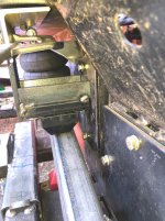
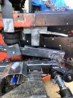
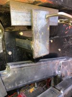
• Please be sure to read the rules and adhere to them. Some banned members have complained that they are not spammers. But they spammed us. Some even tried to redirect our members to other forums. Duh. Be smart. Read the rules and adhere to them and we will all get along just fine. Cheers. :beer: Link to the rules: https://www.forumsforums.com/threads/forum-rules-info.2974/

Astro van cat conversion

Snowy Rivers

Well-known member
I would agree.....
The castings are thinner than the old "Bricks" used in decades past.

Now here is a question I am hearing multiple answers for...

HEAD BOLTS
The bolts that came out of the Vortec are marked with the standard 6 marks in the head indicating a grade 8 bolt.

GM says that the bolts are to be torqued to 20 ft lb and then using a torque angle meter tightened to so many degrees more
55" on the small bolts, 65" on the medium bolts and 75" degrees on the long ones.

The net is full of statements on these bolts being TORQUE TO YIELD "TTY"
GM TECH bulletin says the bolts may be reused as long as they are in good condition and the threads are not damaged or the bolts stretched....

The L31 VORTEC head bolts look just like the head bolts that small block Chevies have used for many decades.

We used to torque to 20 lbs on pass 1........45 lbs on pass 2 and then finish with 65 lbs on pass 3

After reading the writeup on the reason for using the torque angle meter .....it makes sense that tightening a specified amount more past the 20 lb pass 1 will put the tension where the engineers think they want it......Every threaded hole is different and torque readings can vary from what the actual tension needed is in the real world.

I am quite familiar with TTY bolts and have replaced them in several engines that use them....

From what I can glean from all the articles on the subject....There seems to be a lot of folks that believe that just because the mfg says to use a Torque angle meter that the bolts are TTY.

This makes a simple job far tougher than it needs to be......
 

Snowy Rivers

Well-known member
Weather was good today (At least for working)
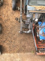
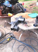
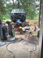
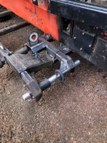
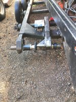
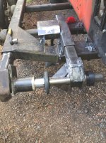
More Fab and machine work on the RH Axle adjuster assembly.

Getting most of the major stuff done on the RH unit.
Tomorrow it's time to machine the actual threaded adjuster unit......

Things are pretty much up to the same level as the LH unit is.

With the rain and crap weather I have had stuff on and off to keep the new bright metal from rusting.

Some pics
 

Attachments

  • RH ADJUSTER FAB19.JPG
    RH ADJUSTER FAB19.JPG
    465.2 KB · Views: 61
  • RH ADJUSTER FAB18.JPG
    RH ADJUSTER FAB18.JPG
    598.3 KB · Views: 58
  • RH ADJUSTER FAB17.JPG
    RH ADJUSTER FAB17.JPG
    581.4 KB · Views: 57
  • RH ADJUSTER FAB16.JPG
    RH ADJUSTER FAB16.JPG
    439.7 KB · Views: 58

Snowy Rivers

Well-known member
More work today.

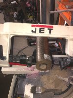
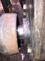
Dug the chunk of brass tube outta the rig....Got it in the saw....Takes about 20 minutes to make a nice clean cut.....minimal taper.
Part is within .010"

Toss in the lathe, trim to .500" thick...bore the inside to 2.002"
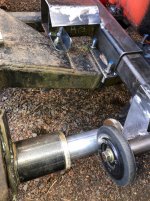
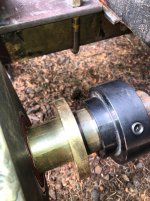
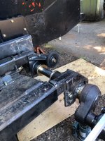
The brass washers go between all the thrust surfaces.

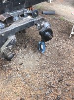
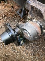
The black round hub is keyed and was originally designed to weld a sprocket to.
The air bag arm will get machined and welded to the hub.
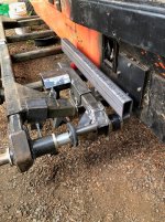
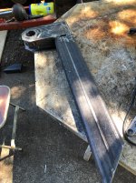
The arm is 2" x 4" x 1/4" Rectangle tube.......
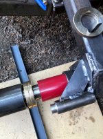
The RED urethane bumper is a Jeep Wrangler suspension bumper......

The Bag arm lays against the bumper when the spindle (Front bogie) is all the way in the down position (Axle off the ground)

Air bag kit ordered this morning.....
Can't go much farther without the bag and brackets .......

The pics for the most part are self explanatory...

The actual axle shaft is in there this time through.

The spindle/casting needs to be heated up hotter than hell and damnation and slipped onto the shaft and then welded.

For now....having that heavy chunk off the axle makes life a tad easier........

The two center brass washers are being held apart by a piece of Exhaust tube.....(I may machine a heavier tube to go in this spot....but the exhaust tube will actually do fine......Just keeps the two adjuster units apart.........

Not shown well...there are marks on the inner slider tube showing where two 1/2" lock bolts will go in to keep the inner adjuster from rattling up and down... (Two nuts weld onto the tube and the bolts thread in to place pressure on the adjuster......

With any luck this will keep the assembly from rattling around....
 

Attachments

  • RHADJUSTER BRASS WASHERS7.jpg
    RHADJUSTER BRASS WASHERS7.jpg
    270.8 KB · Views: 64
  • RH ADJUSTER  BRASS WASHERS6.jpg
    RH ADJUSTER BRASS WASHERS6.jpg
    559.1 KB · Views: 57
  • RH ADJUSTER BRASS WASHERS5.jpg
    RH ADJUSTER BRASS WASHERS5.jpg
    466.9 KB · Views: 58
  • RH ADJUSTER BRASS WASHERS4.jpg
    RH ADJUSTER BRASS WASHERS4.jpg
    459.1 KB · Views: 59
  • RH ADJUSTER BRASS WASHERS3.jpg
    RH ADJUSTER BRASS WASHERS3.jpg
    343.5 KB · Views: 60
  • RH ADJUSTER BRASS WASHERS2.jpg
    RH ADJUSTER BRASS WASHERS2.jpg
    373.3 KB · Views: 62
  • RH ADJUSTER BRASS WASHERS1.jpg
    RH ADJUSTER BRASS WASHERS1.jpg
    309.5 KB · Views: 56

Snowy Rivers

Well-known member
The air bag kit should be here tomorrow.....If ya believe the tracking #####
Picked up the material for the air bag arms today.

2" x 4" x 3/16" tube.
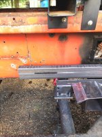
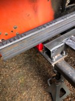
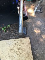
The tube lays parallel to the cat tub and becomes part of the hub assembly that slides onto the axle shaft.

The hub (Black part just outside the tub on the inner end of the axle shaft)..... is keyed to the shaft with a 1/2'" steel key and has a 3/8" hole drilled through the hub and shaft.....A grade 8 bolt goes through the entire assembly to keep the entire assembly together.

One little fly in the ointment.......While looking at the assembly I discovered that getting things all together on the cat were not going to be possible because of the bag arm and the captured key...

Once the final fab work is finished the entire assembly will need to come off the cat (The inner and outer sliders....the inner bolt on assembly stays on the cat)

The assembly will need to be put together on the floor in it's entirety and then slipped into the frame.....the hydraulic adjuster and the mechanical inner adjuster attached at this point.

The air bag and it's brackets can go on after the other equipment is on the frame.
The one piccy shows a black area near the rear of the bag arm.

There will be a slot in the tube.....BOTH SIDES The lower air bag perch will be able to slide fore and aft to adjust the bags location and keep it aligned to a vertical position after the tracks are tightened up...

I want the air bag parts here to get a good feel for position before we go farther with the build.......

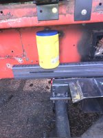
The yellow chocolate jug is close to the air bags size.....Looks good.
The lower bag perch that comes with the kit will need some modifications....OH YEAH.....

I am thinking that a sheet metal shield to protect the bag may well be in order.

The bag should be plenty far away from the bag ....BUTTTTTTTTTTTTTTTTTTTTTTTTTTT.....????
 

Attachments

  • RH AIR BAG ARM4.jpg
    RH AIR BAG ARM4.jpg
    371.5 KB · Views: 52
  • RH AIR BAG ARM3.jpg
    RH AIR BAG ARM3.jpg
    404.7 KB · Views: 61
  • RH AIR BAG ARM2.jpg
    RH AIR BAG ARM2.jpg
    421.6 KB · Views: 51
  • RH  AIR BAG ARM1.jpg
    RH AIR BAG ARM1.jpg
    501.7 KB · Views: 52

Snowy Rivers

Well-known member
Got a wild hair this morning to get the spindle housing on the axle and welded up.
Polished the shaft , added some never seaze on the shaft...Heated the spindle housing up hotter than Hell and damnation .....Figured the unit would slide right on.....Yeah right.

About half way and stuck...
Tried a 5 pound club...nope..no joy.

I let the sucker cool off and came back after breakfast.....

Stuff the axle in the 20 ton press and went after it......I got it within 1/8" of the outer end of the hole.....nope, not going to budge.

Dragged the beast over to the truck shop and we put it in their 50 ton press....Damned well know it moved....

Got the shaft about 1/4" past the end of the casting and called it good......

Lined the hub up with the other axles and then machined a heavy brass spacer from the same material the other thrust washers were made of to keep the assembly where it needs to be......
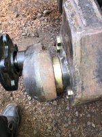
Some pics

Wet weather coming tomorrow....No outside work for a few days me things.

The air bag kit showed up at the post office...Gotta stop and get it tomorrow..
 

Attachments

  • Spindle arm9.jpg
    Spindle arm9.jpg
    538.6 KB · Views: 56
  • Spindle arm8.jpg
    Spindle arm8.jpg
    469.2 KB · Views: 53
  • Spindle arm6.jpg
    Spindle arm6.jpg
    394.8 KB · Views: 51
  • Spindle arm5.jpg
    Spindle arm5.jpg
    315.5 KB · Views: 56
  • Spindle arm4.jpg
    Spindle arm4.jpg
    508.9 KB · Views: 50
  • Spindle arm3.jpg
    Spindle arm3.jpg
    351.9 KB · Views: 58
  • Spindle arm2.jpg
    Spindle arm2.jpg
    436.3 KB · Views: 55
  • Spindle arm1.jpg
    Spindle arm1.jpg
    527.5 KB · Views: 55
  • Spindle arm9.jpg
    Spindle arm9.jpg
    538.6 KB · Views: 53

Snowy Rivers

Well-known member
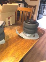
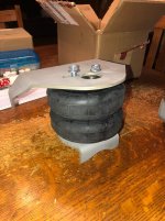
Air bags showed up.
Got them bad boys out of the box....Cute
 

Attachments

  • AIR BAGS2.jpg
    AIR BAGS2.jpg
    321.4 KB · Views: 49
  • AIR BAGS1.jpg
    AIR BAGS1.jpg
    366.3 KB · Views: 49

Snowy Rivers

Well-known member
An interesting twist to things took place yesterday.

Chatting with an old friend who's sons are big time into the off road scene......
The subject of onboard air was being kicked around, which perked my ears up..

The boys had just bought some modified Sanden AC pumps that work sweet as air compressors..
This subject really got my interest as the steering on the cat was heading towards an air system, but the electric pumps are just a tad sketchy, they draw a buttload of power....and they are spendy.

Enter the recently purchased Vortec parts I gathered up for the 406 engine.

The serpentine brackets use a Delphi HT6 compressor.....Sanden makes a direct replacement for that pump in their own line.....

A better pump too..

The mods consist of removing the back head and plugging the oil flow passage to the front end of the pump with a 1/4" set screw loctited in.

Then the front end is removed and the entire assembly is cleaned of refrigerant oil and the area is packed with synthetic grease to lubricate the swash plate, pistons and bearings.. (Thin grease CV-2)

The oil fill plug in the side is drilled and tapped for a grease zerk.....

Reassemble the unit and good to go.

The reports of users seems to be very positive.......

Best part is this bad boy will bolt right onto the bracket that is going back onto the new power plant.

The air valves for steering are already in the cab and several other parts are on the shelf......

I had really thought about scrapping the air system in favor of using hydraulics off the power steering pump.

The cost for the hydraulic valves and other items was not gonna be inexpensive AT ALL....

Air is by far easier to use....and if you spring a leak.....fix the leak and pump up the system......

So I ordered up a Sanden pump.....

Having air on the cat will be nice to take care of the air ride on the front axle.....plus horns and such

The boys I spoke of bought their pumps from Extreme outback....
Well..... I can do the little mods in that pump quite handily.....and not fork out nearly $500.....

We shall see how well this little gizmo works.......
 

Snowy Rivers

Well-known member
Back at it this morning.

Got the RH axle all fitted up to cut the key way for the air bag arm hub....
Needed a few things from town and wanted to get the pistons and such over to the shop so the block can be bored and such....

So we get to the shop and discuss what we are going to do....Piston clearances and such.

I grabbed a piston pin and a rod to see how snug the pin fit was...

OMG that sucker slid right into the rod top end.

These are press fit pins...
I have no idea what went on there.....The rods were all resized.....and I can't believe the other shop did not check the pin bores.,...

Anyway....RODS ARE JUNK.

BUT THE SILVER LINING IN THE BLACK CLOUD....MY MACHINIST JUST HAPPED TO HAVE A COMPLETE MATCHED SET OF 400 SBC RODS IN GOOD SHAPE...$40.....

So at least I did not have to screw around hunting down another set of rods.

Later we stop off at the steel yard and there is a pickup out front with KASSBOHRER on the door.....SNOWCAT ON THE BACK FENDER.

Fella came out and I struck up a conversation.

The outfit is only 10 miles from my place.....

We trucked on over and got a cool tour of the outfit.....

Got to check out a new 600 PB and some smaller machines.

Here is the guys bizz card....if anyone needs Piston Bully goodies
The PB is one stout machine......
 

Attachments

  • PISTON BULLY TUALATIN, Oregon.JPG
    PISTON BULLY TUALATIN, Oregon.JPG
    177.1 KB · Views: 58
  • Like
Reactions: PJL

Snowy Rivers

Well-known member
RH axle is coming together really well.
One small change order had to be made to allow things to be assembled easily.

Getting the air bag arm in turned out to be more of a pain than I had originally thought....but a simple notch in the inner most thrust washer allows the assembly to be slid in from the outside with the key in the shaft and the inner bushing slid towards the center enough to allow the bag arm to slip in and the thrust washer slipped in with the "added slot" in the washer....

The entire assembly became easy to manage...

The center tube between the inner thrust washers has been removed and a pair of split collars added with a half tube welded to the top halves of the split collars to keep the spacing correct.

The inner thrust assembly now comes out to allow the easy assembly of the entire axle unit.


Tomorrow the axle shaft gets a 1/2" threaded hole in the end and the bag arm gets two 3/8" tapped holes on the inner flange .....

These tapped holes allow the use of a pair of push pull tools to get the bag arm on and off the axle shaft easily without a club.....

Sound complicated....not yet....but I'm working at it.....

After the bag arm tools get done....then the air bag itself gets into the action and we shall see how the bag is going to fit into things in the real world....
The brackets are pretty much a universal set up.....made for pickups....Some modifications required...

This entire arrangement should make for a very sound front suspension.......


I WILL BE GLAD WHEN THIS STUFF IS DONE....

The location of the air bag is farther back than I would have liked....but the starter access port and the exhaust access port just would not permit it to be any closer to the front...

But at least both sides can be made the same......
 

Attachments

  • Bag arm assembly5.jpg
    Bag arm assembly5.jpg
    362.8 KB · Views: 53
  • Bag arm assembly4.jpg
    Bag arm assembly4.jpg
    462 KB · Views: 48
  • Bag arm assembly3.jpg
    Bag arm assembly3.jpg
    466.1 KB · Views: 50
  • Bag arm assembly2.jpg
    Bag arm assembly2.jpg
    431.6 KB · Views: 47
  • Bag arm assembly1.jpg
    Bag arm assembly1.jpg
    342.8 KB · Views: 47
Last edited:

Snowy Rivers

Well-known member
More work done on the RH axle
The push pull bolt holes drilled and tapped.
The unit reassembled and the air bag positioned SORT OF WHERE IT WILL GO.....
Gotta fool with the bag and brackets to get the angle of the dangle right.

Likely going to need to make the lower bracket a pivoting item, to allow the bag to swing and stay straight.

WE SHALL SEE.

The two brass thrust washers in the middle under the goat wheel are where the new split collars will go with a 1/2 round tube welded between.

The design change worked great.....the shaft slides in sweet....insert the key then back the assembly up until the bag arm fits in.....add in the brass washer with the notch and pull the bracket onto the shaft with the draw bolt.....

The new collars will be here in a few days.

Exactly how the final incarnation of the air bag bracket will end up is still a guess.....But some cardboard mock up and major imagineering should gitterdone.

The big guess is getting the connection of the bag lower perch to the bag arm such that the track adjuster slides and allows the perch to be adjusted to "The sweet spot"......The bag can not be allowed to shift sideways.....A slight accordion bend can work.....

The 1/2" grade 8 bolt in the bag arm shaft boss is only to keep the arm from shifting on the shaft....THRUST

The 1/2" key in the shaft does the heavy lifting and deals with the torque of the arm.

Some pics
 

Attachments

  • RH ASSEMBLY NEARING COMPLETION8.jpg
    RH ASSEMBLY NEARING COMPLETION8.jpg
    368.6 KB · Views: 59
  • RH ASSEMBLY NEARING COMPLETION7.jpg
    RH ASSEMBLY NEARING COMPLETION7.jpg
    311 KB · Views: 53
  • RH ASSEMBLY NEARING COMPLETION6.jpg
    RH ASSEMBLY NEARING COMPLETION6.jpg
    353.5 KB · Views: 58
  • RH ASSEMBLY NEARING COMPLETION5.jpg
    RH ASSEMBLY NEARING COMPLETION5.jpg
    396.2 KB · Views: 58
  • RH ASSEMBLY NEARING COMPLETION4.jpg
    RH ASSEMBLY NEARING COMPLETION4.jpg
    410.3 KB · Views: 49
  • RH ASSEMBLY NEARING COMPLETION3.jpg
    RH ASSEMBLY NEARING COMPLETION3.jpg
    317.4 KB · Views: 58
  • RH ASSEMBLY NEARING COMPLETION2.jpg
    RH ASSEMBLY NEARING COMPLETION2.jpg
    373 KB · Views: 49
  • RH ASSEMBLY NEARING COMPLETION1.jpg
    RH ASSEMBLY NEARING COMPLETION1.jpg
    351.9 KB · Views: 57
Last edited:

Snowy Rivers

Well-known member
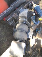
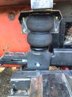
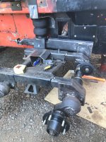
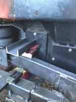
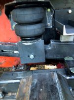
BAG GETTING IN THE ACTION NOW....
The fit came out far better than one could ask for...(You can ask.....rarely get it though)

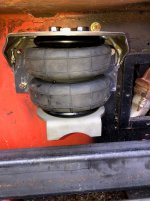
The bag mount snuggled up well right under the front cab mount on the tub......the one bolt that catches the battery tray is easily accessed above the bag mount.....Pure accident.....yeah it was....

I compressed the bag fully and screwed a pipe plug into the air feed port......This gave a good idea of where we were on things with the bag at full compressed......

The lower bag perch is pretty well going to do what I want it too.
The perch needs some mods....as does the bag arm.

Bag arm is coming off again and a bit of work near the rear end of it to cut out a long notch on an angle to give a bit more room for the perch to articulate as the arm raises.

We may be able to get a touch more travel on the spindle too.....

The ratio of the spindle housing to the bag arm is such that the throw is not what I would really like.....but these things happen and any easy remediation is not forth coming due to the stuff up front thats in the way.......Chit happens...


The bag mount bolts to the tub with four 3/8" bolts....current plan is to add a small piece of angle to the outer edge of the top outer portion of the mount just outboard of the air inlet port and sneak it up and let it share the front bolt on the cab mount.

Already there, and in a very good place to tie things together and keep the area strong.....with the cab mount tubes directly above the air bags....life is good.......

Some pics..

Oh yeah....this bad boy is going to change a bit more before the paint hits it.....but it's getting where I want it.......

And yess...we will make the other side just the same.... referencing the front cab mount bolt hole as a datum point.

It would have been nice to have been able to keep the bag arm much shorter.....life sucks some times eh ????

Pics
 

Attachments

  • AIR BAG MOUNTING5.jpg
    AIR BAG MOUNTING5.jpg
    421.5 KB · Views: 49
  • AIR BAG MOUNTING3.jpg
    AIR BAG MOUNTING3.jpg
    380.7 KB · Views: 50
  • AIR BAG MOUNTING2.jpg
    AIR BAG MOUNTING2.jpg
    321.2 KB · Views: 53
  • AIR BAG MOUNTING1.jpg
    AIR BAG MOUNTING1.jpg
    334.5 KB · Views: 51

Snowy Rivers

Well-known member
Not much done today....not for the lack of wanting.....Broke the blade on the saw.....nobody had any decent blades in stock.

Finally landed a couple blades this afternoon late.

Back at it...

Got the brass thrust washers cut for the left side axle....(While the blade was fresh)
Cut the outer bag support brackets too...

Bolt hole drilled and the bracket fit.......bag removed and the assembly can be tacked up now.
That and other stuff can wait until tomorrow.

Cool thing did happen....while were were out searching for a saw blade we stopped at a garage sale.....scored a nice little two bolt bar puller in nice shape.....It will work perfectly to remove the bag arm from the axle shaft...... $3 ....NUFF SAID....A good day....
 

Attachments

  • TOP BAG MOUNT2.JPG
    TOP BAG MOUNT2.JPG
    250.1 KB · Views: 52
  • TOP BAG MOUNT1.jpg
    TOP BAG MOUNT1.jpg
    335.6 KB · Views: 49

Snowy Rivers

Well-known member
Short day today....Domestics ya know.

Got the new little puller on the bag arm....Sweeeeeeeeet....works like a charm.....

Did the cope job on the arm to provide a tad more room for the lower bag perch to articulate as the arm goes through the arc .....

The latest plan is to add a solid bar inside the tube about 6" long that the pivot bolt on the bag perch will go through.....just about centered. The bar will spread the load out over the bottom of the beam......

The center bar gets a threaded adjuster rod/and double nut.

The adjuster will keep the bag perch right on location once adjusted (After track adjustment is where it needs to be)

Next the arm goes back on and the bag/perch get looked at seriously and the perch gets massaged a bit.
Side plates....and a couple spacers to keep the assembly straight....

The bag arm gets a slot cut (Both sides) to allow for the assembly to move with the track adjustment and the bag to stay correctly positioned....
THIS PLAN HAS BEEN COOKING FOR A WHILE.....

Looking at the area that needed to be notched in the bag arm.....The sharp corner at the front end of the cut.....going to fish plate that area on both sides and perform a trick to hopefully eliminate any crack issues......

Seems that nearly every cat has something that cracks.....

OLD RACE LOGIC....."IF IT AIN'T MOVING....SOMETHING IS BREAKING"

A little flexing is fine.....to a point.
Get a crack.....weld it up and pile on the iron.....CRACK GOES SOME PLACE ELSE......USUALLY A WORSE PLACE........
 

Attachments

  • Bag arm mods3.jpg
    Bag arm mods3.jpg
    405.8 KB · Views: 48
  • Bag arm mods2.jpg
    Bag arm mods2.jpg
    411.8 KB · Views: 50
  • Bag arm mods1.jpg
    Bag arm mods1.jpg
    413.1 KB · Views: 50
  • Bag arm mods4.jpg
    Bag arm mods4.jpg
    829.5 KB · Views: 47

Snowy Rivers

Well-known member
Plugging away at it.
The air bag mount is just about completed....The lower bag mount needs to get drilled for the cross bolt.
I got some plumbing parts and a schrader valve to air up the bag.....

Set the bag at 8" high (Max spec.)
Some fiddling with the adjustments to get the location of the slot in the bag arm correct.

Measured the adjustment cylinder (Grease) and set the location of both the inner and outer adjusters at MINIMUM and welded a chunk of key stock on the sliders to be a minimum stop.....

Some pics

Pic 5 from the left has a good shot of the little Goat Wheel.(Safety idler) for the inner front of the track as it rounds the front road wheel....
Adjacent to the air bag lower mount is the little platter that gets a UHMW piece that serves to keep the track from sagging or ??? down into the inner adjuster assembly.....

The extra baggage that came with the redesigned version of the axle created some interesting WHAT IF scenarios....

I think the bases have been covered by now......I DO HOPE SO.....
 

Attachments

  • RH ASSEMBLY NEARING COMPLETION13.jpg
    RH ASSEMBLY NEARING COMPLETION13.jpg
    382.2 KB · Views: 53
  • RH ASSEMBLY NEARING COMPLETION12.jpg
    RH ASSEMBLY NEARING COMPLETION12.jpg
    453.2 KB · Views: 51
  • RH ASSEMBLY NEARING COMPLETION11.jpg
    RH ASSEMBLY NEARING COMPLETION11.jpg
    441.6 KB · Views: 50
  • RH ASSEMBLY NEARING COMPLETION10.jpg
    RH ASSEMBLY NEARING COMPLETION10.jpg
    405.8 KB · Views: 56
  • RH ASSEMBLY NEARING COMPLETION15.jpg
    RH ASSEMBLY NEARING COMPLETION15.jpg
    319.7 KB · Views: 55
  • RH ASSEMBLY NEARING COMPLETION14.jpg
    RH ASSEMBLY NEARING COMPLETION14.jpg
    238.8 KB · Views: 64
  • Like
Reactions: PJL

Snowy Rivers

Well-known member
TO DAMNED HOT OUTSIDE TO WORK ON THE CAT..100 F PLUS ARRRRRRRRRRRRRRRRRRRRGH

Did get a package today though in the mail....

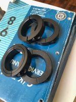
The 4 split collars that will form the center axle spacers came.....

As soon as this heat wave abates....the center spacers for the axle adjusters can be fabricated.

Staying cool at this point.

Gonna try getting out at the butt crack of dawn tomorrow and seeing what can get done.....
 

Attachments

  • CENTER SPACER COLLARS.jpg
    CENTER SPACER COLLARS.jpg
    369.6 KB · Views: 48

Snowy Rivers

Well-known member
Well the plan to be on the cat at THE BUTT CRACK OF DAWN...GOT SCUTTLED.
Son in law called up and shared the bad news...their AC took a dump...

With 110 to 115 F expected today...NOT GOOD.

After we discussed the issue I was near certain that the run capacitor on the compressor had gone south....

Head on over and we rip the cap out....
A quick check.
45/5 440 volt cap.
The 5 part was sweet at 4.99 uF (Microfarads)

The 45 part was at .73.....DEAD PLAYER.

Nobody has a cap on a Sunday.
They found a local HVAC fella that had some parts....NOT EXACTLY RIGHT ....But was able to jury rig 2 caps to obtain what was needed.
$325 and their house is cooling off nicely again.....

To bloody hot outside to go out and work......

Maybe tomorrow morning.....
The excess heat is supposed to moderate in a day or so....
 

Snowy Rivers

Well-known member
Been more like "Smile...you're on candid camera" around here.

Any time something goes buzzwhack.....my phone rings.
The daughter knows my experience with just about most things mechanical, electrical and plumbing.

Yeah.....would make an interesting show.

Never fails......Sunday....or weee hours and chit breaks.
 

Snowy Rivers

Well-known member
Nothing done the past couple days....AT ALL.....Yesterday it was 91 F outside at 5 am and by 5 pm it was 109 F

I hate hot weather with a passion.....and this was just nuts..

The heat broke last night with a stiff West wind and 63 F this morning.
With luck things can get back to a more normal pace.....
 

Snowy Rivers

Well-known member
COOL WEATHER TODAY........69 F as I write this.....YESSSSSSSSSSSSSSSSSSSSSSSSS better than the 109 F Monday...

GOT THINGS GOING ON TODAY TOO...

Back to work on the RH front axle......

The assembly needed to come apart twice today for machining and more design work.
There will likely be a few more together and apart go rounds before the paint hits the steel......

The red urethane bottom stop was near the rear of the bag arm....moved it.....gonna move it back to where I had it.....

Machined the slots in the bag arm for the lower perch to slide on a 1/2" grade 8 bolt.
Needs to be a slight bit of machining in the rear portion of the lower bag perch to allow some clearance.....

The next step is to build the lower bag perch adjuster bar assembly.

This bar goes inside the bag arm and has a 1/2" threaded rod that allows the bar to slide fore and aft.
The bolt that holds the lower perch passes through the inner bar.

This allows the perch to be located in the best position once the track is adjusted......

With the lower perch located correctly the bag will be nearly straight up and down with only a slight arching to the bag as it nears the fully compressed position .....(Bag arm full up position....bag compressed )

The stop arrangement to arrest the bag arm at it's full up position is still on the drawing board.

At present the only easy to execute plan is a CHAIN with a eye bolt and a urethane biscuit attached and adjustable to restrain the arm at the upper most position.

Big issue with this entire assembly is the fact that it is adjustable 4-1/2" forward to tighten the track......and everything connected with the assembly MUST GO ALONG FOR THE RIDE and stay in it's proper orientation.....

Not difficult.....just a PITA to get all the little parts to talk to one another is all.

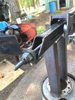
The lower bag perch inner adjuster has been on the sketch pad for a few days now.......And I finally came up with an idea to allow ease of adjustment and an easy way to build it..... Must be able to be adjusted with a GEAR WRENCH from the rear side of the assembly....and be totally removable.....

Came up with a slotted bracket that the adjuster nut slips into and has a cotter pin through the top to retain the nut assembly.

Then a standard 1/2" nut to jam the assembly once it is adjusted to suit.

I will get pics of this stuff as the parts get machined....

Actually pretty simple little gizmo.....


I have to say this.....without the mill and the lathe this would not be possible......just too many special parts.....
 

Attachments

  • RH ASSEMBLY NEARING COMPLETION18.jpg
    RH ASSEMBLY NEARING COMPLETION18.jpg
    408.1 KB · Views: 58
  • RH ASSEMBLY NEARING COMPLETION17.jpg
    RH ASSEMBLY NEARING COMPLETION17.jpg
    489.5 KB · Views: 57
  • RH ASSEMBLY NEARING COMPLETION16.jpg
    RH ASSEMBLY NEARING COMPLETION16.jpg
    401.2 KB · Views: 63

Snowy Rivers

Well-known member
Got in the machine shop early this morning and started gathering parts for the bag perch adjuster assembly

I had made a similar unit for the inner track adjuster and made a change to the design (Longer) and the original one was laying on the bench.....perfect for this application....Actually needed to shorten it a bit.

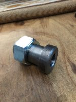
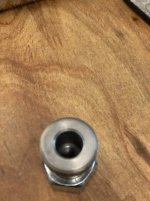
The nut is a 1" with the threads bored out...Nut slides onto the nut unit and gets welded at the outer end.

Headed to town and picked up more steel to finish the adjuster bracket on the bag arm.
Some 1-1/2" X 2" steel tube for the inner bar that goes inside the arm.

Got some domestics this afternoon...not much going to happen the rest of the day....

A few pics of the little machined part.

Decided that using 5/8" threaded rod would be acceptable since we already had the one part nearly complete anyway.....A bit overkill...Oh well
 

Attachments

  • bag arm lower perch adjuster2.jpg
    bag arm lower perch adjuster2.jpg
    222.9 KB · Views: 46
  • bag arm lower perch adjuster1.jpg
    bag arm lower perch adjuster1.jpg
    232.3 KB · Views: 52
  • bag arm lower perch adjuster3.jpg
    bag arm lower perch adjuster3.jpg
    506 KB · Views: 53

Snowy Rivers

Well-known member
Bag arm back off the axle "AGAIN" and in the vice to work on the perch adjuster assembly.....
Machining....more fooling and tweaking to get things working smoothly......

The original plan called for an 8" long bar to slide inside the bag arm ( 1-1/2" X 2" x 8" ) but the size was a bastard.....and nothing available at the yard.
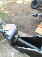
Found some box tube the right size.....BINGO....Welded a small piece of flat bar in the end with a hole for the threaded rod to go.
Welded a nut on the end of the assembly.....add a jam nut to keep the rod indexed.....Will Loctite the thread rod at final assembly...

The idea is to make the rod replaceable if need be.....(The inner tube can slide out the front of the bag arm)
Originally I had thought of slotting the adjuster nut mounting tab and caging the adjuster nut assembly with a cotter pin or ?????

Screw it.....Bored a 1-1/8" hole...inserted the nut parts and welded it together......IT CAN BE CUT MID SPAN ON THE BIG NUT AND REMOVED IF REQUIRED TO BE REPLACED LATER......Liberal application of grease to the threads periodically should give this unit a good life span......

The bag perch has two spacers to set the perch at the correct distance from the Cat tub ( Top and bottom bag ends are looking at each other.....inner spacer is narrower than the outer one to get things where they need to be)

Tested the travel of the adjuster from end to end.....Smooth as a babies butt.......... :thumbup:

Tomorrow the arm goes back on the axle.....Bolt goes through the perch as it is in the RH PICCY NYLOCK ON THE BACK NEXT TO THE TUB........With the lower perch fastened to the bag the entire bag assembly can bolt back to the cat chassis.....Then the arm can be assembled to the axle easily without having to deal with the bag being attached to the arm (WE TRIED IT THAT WAY A COUPLE TIMES.....BULL SH** too much work dealing with all the parts together...... THAT ARM IS NOT LIGHT)
 

Attachments

  • RH AIR BAG PERCH ADJUSTER3.jpg
    RH AIR BAG PERCH ADJUSTER3.jpg
    305.4 KB · Views: 55
  • RH AIR BAG PERCH ADJUSTER2.jpg
    RH AIR BAG PERCH ADJUSTER2.jpg
    230.7 KB · Views: 53
  • RH AIR BAG PERCH ADJUSTER1.jpg
    RH AIR BAG PERCH ADJUSTER1.jpg
    263.3 KB · Views: 53

Snowy Rivers

Well-known member
Reassembled the axle components this morning early.
Looks great....

Went in the shop to get some tools.....The machine shop was a total mess......Tired of dragging chips and metal shavings all over on my shoes.
TIME TO CLEAN THE SHOP.
Swept the floor, vacuumed the machines and hauled off two 5 gallon buckets of crap. Hauled off several cardboard boxes left from materials that came in with goodies for the cat

Actually discovered a lot of room.
Getting ready to start building the 406 engine for the cat.....Need a place to work.....
Son in law was over and fetched the engine stand down out of the rafters for me.......

Old bones are done for the day.....
 

m1west

Well-known member
GOLD Site Supporter
Reassembled the axle components this morning early.
Looks great....

Went in the shop to get some tools.....The machine shop was a total mess......Tired of dragging chips and metal shavings all over on my shoes.
TIME TO CLEAN THE SHOP.
Swept the floor, vacuumed the machines and hauled off two 5 gallon buckets of crap. Hauled off several cardboard boxes left from materials that came in with goodies for the cat

Actually discovered a lot of room.
Getting ready to start building the 406 engine for the cat.....Need a place to work.....
Son in law was over and fetched the engine stand down out of the rafters for me.......

Old bones are done for the day.....
Where is a good place to get rid of lathe crap
 

Snowy Rivers

Well-known member
Shavings and such (Brass, steel, aluminum) I just toss it in the weekly garbage can.

I don't have enough to turn it in for scrap....

Just enough to make a mess.

I am getting ready to start building the bag arm and other goodies for the left side now....I wanted the shop to be clean...RELATIVE TERM....
 

Snowy Rivers

Well-known member
Starting to think about the drill fixture needed to drill the steam holes in the Vortec heads.

The 400 SBC has Siamese cylinder bores and there are two steam holes between each of the cylinders (3 sets of holes in each head)
These go through to the water jacket.

I may make a jig....or make a pair of brackets that bolt to the ends of the heads to allow them to index the head decks to 20 degrees off level.

The holes closest to the intake side need to be drilled towards the exhaust ports to intersect with the water jacket.....

Just more stuff to think about.

The little 406 Vortec is going to get painted CAT YELLOW....Valve covers ( Stock GM Vortec center bolt type) are getting Black wrinkle paint....Aluminum intake will stay bright alloy....Pan is anodized a bright silver.

The air filter is still in the thinking stage.....May use a aluminum top hat on the Quadrajet with a right angle and aim it back down the tunnel in the cab....We need a hot air supply to feed the carb too...

The Vortec aluminum intakes for 4 barrels do not have heat riser passages......DO I HEAR CARBURETOR ICING ISSUES....YEAH BUDDY...
I think a heat shroud off one of the exhaust pipes can supply plenty of hot/warm air to keep icing in check......
 

Snowy Rivers

Well-known member
A couple pics from yesterday after reassembling the RH axle.
To cut to the chase here.
There are a few things left to do before the assembly can be removed for the final time, painted then reinstalled.

(1) The inner track adjuster assembly "Threaded unit" still; needs to be finished
(2) The outer adjuster grease cylinder needs to be reassembled with the new seals and installed
(3) The UHMW pad needs to be cut and fitted to the track over travel safety shelf (Little box structure welded to the inner adjuster slide tube)
(4) Thrust cap on inner end of axle shaft.....****Slides over end of the axle and is held in place by the center bolt in the end of the axle.....Serves two functions......Protects the shaft from damage and loads the bag arm inward against the through bolt to help prevent any wobbling on the shaft and the key.****

(5) Still need to add the upper limit travel stop......I think this can be added to the cover plate that goes over the access port to the exhaust connection to the manifold.....Still thinking about this bad boy.....
Now that the bag perch adjuster is in, I want to air up things and see just where the arm ends up when I jack the spindle up to the point that it lifts the cat..... Basically we have to sort out the amount of actual spindle travel and go from there.

The actual travel is a mystery.....I have no idea how much movement the original set up allowed the spindle to travel up and down.
The short 6" arm on the front axles certainly does not allow much...
As long as there is flex in things to prevent damage to the chassis.....we should be good.
THIS IS NOT...going to be a long travel BAJA cross country suspension.....A new replacement axle at an affordable price would have been great......Not going to happen.

(6) Paint and then grease the moving parts (Urethane bushings, shaft and such) Using very sticky waterproof silicone grease....

Getting close.......

Then we pick up the tools and move back to the LH side and go again.
Finishing the left side will be much easier......NO DESIGN WORK TO DO.....JUST BUILD THE PARTS AND INSTALL THEM...

OH YES...Detailed drawings are made of each piece as they have been made....SO WE CAN DO IT AGAIN...... :thumbup:
 

Attachments

  • RH ASSERMBLY NEARING COMPLETION20.jpg
    RH ASSERMBLY NEARING COMPLETION20.jpg
    344.1 KB · Views: 59
  • RH ASSEMBLY NEARING COMPLETION19.jpg
    RH ASSEMBLY NEARING COMPLETION19.jpg
    421.9 KB · Views: 55

Snowy Rivers

Well-known member
More work done.....actually more planning than work...but some work done....

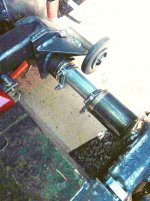
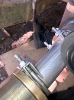
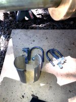
Cut the original center thrust spacer tube in half....picked up the exhaust clamps......

Got that Gizmo bolted on . :thumbup: yesssssss...Simple and easy to get on and off.
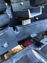
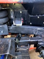
Operated the suspension through a fair range of the available arc......The lower bump stop is fine where it is..

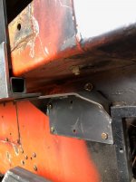
The upper stop is going to fasten to the cover plate I mentioned earlier.

A few pics of things.

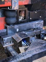
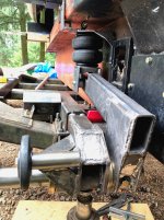
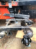
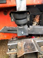
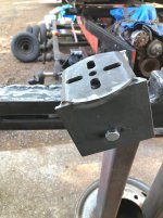
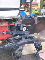
The upper bump stop bracket needs to be kept as short as possible and the outer mounting foot will fasten under the upper edge of the tub.....This thing needs to be OUT OF THE BATTLE ZONE .....The edge of the track is close......The track inner edge runs by close to the inner adjuster tube......
There is plenty of room for everything.....BUT I do not want to deal with a train wreck....

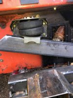
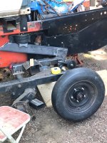
At any rate.....the air bag and arm articulate really nice from full down position (Bag at 8") to a spot that places the bag at about 4-1/2" (2-3/4" is fully compressed)

The bag is running in the sweet spot and the lower perch pivots really well..

About 5-7 pounds of air in the bag and I can lift the cat off the jack stand with hydraulic jack under the spindle......
That bag arm has a lot of mechanical advantage.... about 18-20" arm and the spindle is 6" off center of the axle......
Anyway
Pics...

More tweaking on the upper bump stop bracket..
 

Attachments

  • Upper stop4.jpg
    Upper stop4.jpg
    281.9 KB · Views: 43
  • Upper stop3.jpg
    Upper stop3.jpg
    304 KB · Views: 44
  • Upper stop2.jpg
    Upper stop2.jpg
    308.4 KB · Views: 48
  • Upper stop1.jpg
    Upper stop1.jpg
    339.4 KB · Views: 48
  • Center spacer with clamps3.JPG
    Center spacer with clamps3.JPG
    475.6 KB · Views: 52
  • Center spacer with clamps2.jpg
    Center spacer with clamps2.jpg
    258.8 KB · Views: 51
  • Center spacer with clamps1.jpg
    Center spacer with clamps1.jpg
    367.3 KB · Views: 57
  • Like
Reactions: PJL

Snowy Rivers

Well-known member
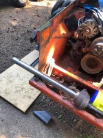
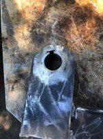
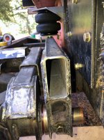
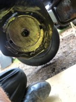
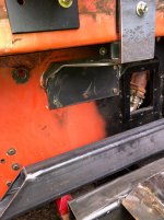
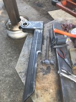
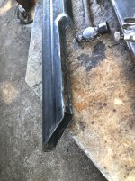
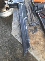
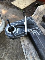
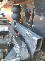
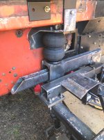
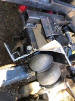
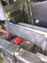
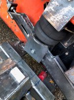
Got to work on the upper bump stop bracket.

Dropped the air pressure off the air bag for the most part so I could get the arm up into the upper reaches of it's arc......

Got the parts figured out and cut.....
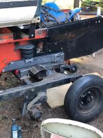
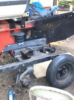
This poor old Packer has more damned holes in it from the blade mount and other stuff bolted on THAT GOT TOSSED....Trying to use as many of the original holes as possible......
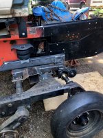
The upper bumper is black urethane....only because the set was available cheaper than the red ones....Same brand (Energy)

The parts are tacked together and clamped in place now.

Tomorrow the cover plate gets removed and the paint buffed off....then the bracket parts get tacked up.....OFF AND TO THE TABLE TO BE WELDED......

The next part to be tackled will be the adjust rod for the inner track adjuster.
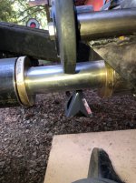
Making a revision on the plan too.

Going to go with something very similar to what ended up on the bag perch adjuster.

Simpler and will be easier to replace if need be.....

The original system with the grease cylinder was simple....but the presentation was just crude.

I have a pair of Heim joints coming for the two inner adjusters.

That will make things self aligning and much easier to work with......
 

Attachments

  • UUPER STOP10.jpg
    UUPER STOP10.jpg
    349.4 KB · Views: 46
  • UUPER STOP8.jpg
    UUPER STOP8.jpg
    385.6 KB · Views: 48
  • UPPER STOP9.jpg
    UPPER STOP9.jpg
    354.2 KB · Views: 50
  • UPPER STOP7.jpg
    UPPER STOP7.jpg
    340 KB · Views: 46
  • UPPER STOP6.jpg
    UPPER STOP6.jpg
    396.4 KB · Views: 47
  • UPPER STOP5.JPG
    UPPER STOP5.JPG
    335.7 KB · Views: 49
Top