
-
Please be sure to read the rules and adhere to them. Some banned members have complained that they are not spammers. But they spammed us. Some even tried to redirect our members to other forums. Duh. Be smart. Read the rules and adhere to them and we will all get along just fine. Cheers. :beer: Link to the rules: https://www.forumsforums.com/threads/forum-rules-info.2974/
You are using an out of date browser. It may not display this or other websites correctly.
You should upgrade or use an alternative browser.
You should upgrade or use an alternative browser.
Power Beyond?
- Thread starter johnday
- Start date

I know enough about hydraulics to get myself into trouble so my explination will be the simplistic view. I will leave it to MadReferee or someone else to give the more technologically correct answer.
Basically 'power beyond' is a type of valve that allows for a hose connection that allows for hydraulic fluid to flow past the valve and power something beyond that valve.
Basically 'power beyond' is a type of valve that allows for a hose connection that allows for hydraulic fluid to flow past the valve and power something beyond that valve.
MadReferee
New member
Technically speaking, power beyond is a feature on a directional control valve that allows the pressure gallery to be isolated from the tank gallery and be carried over to an additional valve - usually another directional control valve.
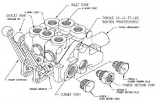
The implementation of the power beyond feature varies with valve type and manufacturer. However the most common arrangement is to install a threaded plug or sleeve that blocks the internal connection between the pressure and tank galleries inside the valve. This creates two outlet ports, the power beyond and the return to tank. The power beyond port is then used to supply high pressure pump flow to the additional directional control valve. The return to tank port returns neutral pressure flow from the work ports (from the cylinders) back to the tank reservoir.
That's the technical description and is an edited version of what is available from "The Insider Secrets to Hydraulics".
In simple laymans terms, if you have more than one valve in a series hydraulic circuit, all valves except for the last must have power beyond capability since neutral pressure exhaust fluid from the valve work ports cannot drive the next valve in the circuit.
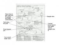
This is a pic i made up for Junk. The grapple is on the pwoer beyond circuit, basically it just means that the unused pressurised fliud gets directed to the first valve, if it isnt used by the first valve it is sent on to the other. If it is used b the first vavle it gets sent ot the tank and not to the second vavle
Attachments
Guys, I see. It's basically nothing more than tapping into your diverter valve, and running a pressure line to another one. Then routing return lines back to the reservoir.
Jim, I see in your drawing that the pressure line to the "aux" diverter, is on the downstream side of the original one. Would it be better to tap off ahead of the original diverter?

Jim, I see in your drawing that the pressure line to the "aux" diverter, is on the downstream side of the original one. Would it be better to tap off ahead of the original diverter?
MadReferee
New member
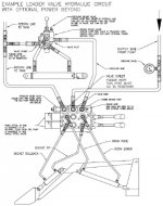
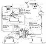
That drawing comes directly from the Prince SV parts manual. You can download it yourself by going to :
http://www.princehyd.com/portals/0/products/valves/svmanual.pdf
http://www.princehyd.com/portals/0/products/valves/svmanual.pdf
John,
The second valve is plumbed into the power beyond port, not the tank return, of the first valve. You could put the second valve first and plumb the first vavle into the power beyond port of the second. The idea is that the fluid that comes out of the cylinders does not go to the second valve in line. The second valve only gets new pressure fluid.
For example, when the first valve is in open centre nutral the fluid goes through that vavle, throught the power beyond port into the seond valve. here the fluid would go straight through the vavle, unless it is operated as normal, then the fluid is sent back to the tank. If the first is operated then the fluid is used into the cylinders. The fluid that comes out of the cylinders is exhauseted to the tank and not to the second valve. The second valve recieves no fluid as the first one is operated. Thus, it is usual to put the most important valve first. So you would put the loader beofre the grapple, as a result, if you are using the lift on the loader the grapple will not clamp, but as soon as you let off the lift the grapple will recieve the fluid through the power beyond port and close.
Man, lots of writing there
Big Dog, I attached a couple pics for ya! As madref says, they are just from the prince instruction sheets
Attachments
MadReferee
New member
johnday said:Guys, I see. It's basically nothing more than tapping into your diverter valve, and running a pressure line to another one. Then routing return lines back to the reservoir.
Jim, I see in your drawing that the pressure line to the "aux" diverter, is on the downstream side of the original one. Would it be better to tap off ahead of the original diverter?
All valves must be in series. You just can't tap off at any place. All valves except for the last one must have power beyond. The last one doesn't need it since it's output goes directly to tank. The only "tap" you can make is for the return to tank line since this is a neutral pressure line. No other pressure lines may be teed or tapped into.
Excellent info. Once seeing a diagram, it makes sense.
Greg; Yeah, it's similar to an EHC system. Just a lot simpler, glad you said EHC and not DEH. I hate Westinghouse hydraulic controls. And their seal oil systems are even worse.
EHC--ElectroHydraulicControl system General Electric
DEH--DigitalElectroHydraulic system Westinghouse
These are both hydraulic systems for steam turbine controls, opening and closing steam admission valves to tubines. Two different manufacturers, two different ways to do the same thing.
Seal Oil System-- Used on Hydrogen cooled generators, to keep the H2 where you want it, inside the generator, and not floating around the turbine house.
Greg, just thought I'd throw that in since most people wouldn't be familar with power plant jargon. 

Greg; Yeah, it's similar to an EHC system. Just a lot simpler, glad you said EHC and not DEH. I hate Westinghouse hydraulic controls. And their seal oil systems are even worse.
EHC--ElectroHydraulicControl system General Electric
DEH--DigitalElectroHydraulic system Westinghouse
These are both hydraulic systems for steam turbine controls, opening and closing steam admission valves to tubines. Two different manufacturers, two different ways to do the same thing.
Seal Oil System-- Used on Hydrogen cooled generators, to keep the H2 where you want it, inside the generator, and not floating around the turbine house.
Greg, just thought I'd throw that in since most people wouldn't be familar with power plant jargon.
johnday said:Excellent info. Once seeing a diagram, it makes sense.
Greg; Yeah, it's similar to an EHC system. Just a lot simpler, glad you said EHC and not DEH. I hate Westinghouse hydraulic controls. And their seal oil systems are even worse.
EHC--ElectroHydraulicControl system General Electric
DEH--DigitalElectroHydraulic system Westinghouse
These are both hydraulic systems for steam turbine controls, opening and closing steam admission valves to tubines. Two different manufacturers, two different ways to do the same thing.
Seal Oil System-- Used on Hydrogen cooled generators, to keep the H2 where you want it, inside the generator, and not floating around the turbine house.
Greg, just thought I'd throw that in since most people wouldn't be familar with power plant jargon.
I've worked both GE and Westinghouse and GE wins by far, I'm with you John!
Paul; Poor choice of words on my part. I'll see if I can clear up what I meant. If you have a series of valves without power beyond, it appears you could tap in with a tee on the high pressure supply line, and pipe to where ever you need it. Then pipe to the return back to tank. I guess I'm describing a header type arrangement [parallel?], where you would have a common HP supply header, and a common LP return header.MadReferee said:All valves must be in series. You just can't tap off at any place. All valves except for the last one must have power beyond. The last one doesn't need it since it's output goes directly to tank. The only "tap" you can make is for the return to tank line since this is a neutral pressure line. No other pressure lines may be teed or tapped into.
Now that I think of it, that's a simplistic version of turbine control systems.
Don't know how I made this so difficult. Guess it sounds sorta cosmic with "Power Beyond"!
HarleyScooter
New member
Hi everyone I just found out about this Forum. My question is on a BX2230 if I hook my rear remotes to the backhoe lines on the back of the tractor do I need a power beyond valve? I do not have a backhoe so the conections do not have to be tee'd.
Thanks Scott
Thanks Scott
MadReferee
New member
HarleyScooter said:Hi everyone I just found out about this Forum. My question is on a BX2230 if I hook my rear remotes to the backhoe lines on the back of the tractor do I need a power beyond valve? I do not have a backhoe so the conections do not have to be tee'd.
Thanks Scott
It depends on how those connections are plumbed in.
Is there a jumper hose that connects the two together when the backhoe is not in use?
Is the 3pt disabled when a backhoe is connected?
Where are the connections plumbed to?
We need more information since this is not a standard configuration.
HarleyScooter
New member
MadReferee, I will copy what someone else once wrote about the rear hyd. lines; Well the backhoe has it's own set of section valves, and the log splitter has it's own as well. The loader valve is not used other than to operate the loader, it doesn't need to be connected for the rear hydraulic to operate. Just like when the loader is off you connect the high pressure "IN" line to the "Power Beyond" line. This power beyond line now gets another line "T"ed into which becomes the rear high pressure carry over "IN" line(part 140 in the diagram). This line has the hose connected to it which can then be connected to the new "RETURN" to pump line(part 170 in the diagram) which is connected to the new hydraulic block(part 040) (Note: the rear hydraulics has no "RETURN" to tank line like the loader does). The rear hydraulics are designed to operate with a standard 1 "IN" 1 "OUT" style valve. If you wish to use a valve that has power beyond capabilities you will need to plumb an additional "RETURN" to tank line for the waste port on the power beyond valve. Also, any valves connected must be "Open Center" style valves. I hope that clears things up.
This explains it better than I could, this is the same thing Junkman did back in 9/04 but he tee'd into the lines I believe, to use the backhoe and rear remotes at the same time. Junkman also used a power beyond open center valve, with a third hose as a return to tank line (again I think). Since I do not have the backhoe, just the pipes and connections to the rear of the tractor, I am unsure if I need the power beyond valve and the extra return line? The two lines do connect when there is no backhoe installed. As far as the 3 PT being disabled when the backhoe line are connected I don't know, but I hope not as that is why I want the rear remotes, to work with the 3 PT attachments.
Thanks
Scott
MadReferee
New member
If the two lines need to be connected when the backhoe is off that means the the pressure line was broken after the loader valve but before the 3pt. You will definitely need a valve with power beyond if you want the 3pt to operate correctly.
The pressure side connector goes to your aux valve's inlet, the other connector goes to your valve's power beyond port, and the outlet of your aux valve need to connect to tank via a tee connector.
Any other connection scheme is incorrect and may or may not work to your, and the system's, satisfaction.
HarleyScooter
New member
Thanks MadReferee, that answers my question. I can start buying parts now.
Happy Holidays
Scott
Happy Holidays
Scott