Re: An introduction/hello and my project.
Hey..
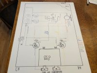
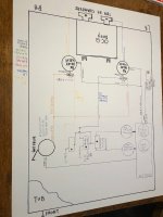
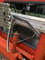
If you are referring to the FOOT brake ???
That is a standard single circuit TREADLE/FOOT valve that is activated by the brake pedal arm in the van.
With the stock van brakes still fully functional the pedal will function...turn on the brake lamps etc.
There is a small bracket that mounts to the pedal arm and pushes on the valve plunger.
This was a simple yet effective way to have full pressure control from 0 to 65 PSI to control the brakes in a varying degree for easy smooth stops without harsh applications.
AS far as the Filter drier goes.
The Regulators shown in the sketch are actually filters as well.
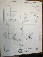
This system is going to evolve as things progress.
I have looked at moisture ejectors, desiccant driers and other air management items.
I wanted to get the basic schematic on paper to be able to look at it and see just how it all looks when it's right in front of me and not just ideas....
Coming from an engineering and machinery building background I like to get ideas on paper and beat things around.
Saves a lot of $$$ in the long haul.
I am sure things will evolve more as we go.
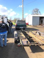
The drive shaft thing.
Actually very simple.
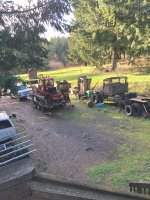
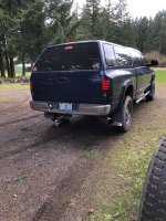
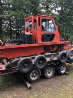
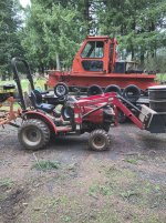
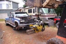
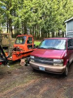
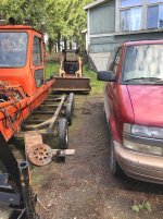
Having the van as a CAT ADD ON....The van chassis is going to sit as close to the top of the 2100's TUB as possible and anchor via the wheel studs to the cat with 4 fabricated mounts.
The Cat differential is quite a bit lower than what can be connected with any realistic driveshaft.
(The van must remain totally intact....so it can roll off the cat and go shopping in a matter of a short time)
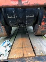
So....a drop box was needed to get the drive lines such that acceptable angles and other drive shaft geometry adhered to.
Main shaft has 2 cv joints with a 3rd CV on the front section (2 piece shaft) The shaft that connects the drop box and the OC12 has a 1410 at the OC12 and a 1350 at the slip yoke in the drop box (Shorty shaft...about a foot long)
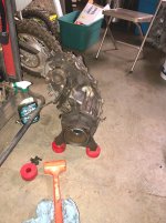
An NP241 transfer case stood on end set into the cat chassis just ahead of the OC12 will give us the ability to use the (What was) the front output flange as our input and the original output slip yoke as the output to the OC12.
The shaft elevation has dropped 10 plus inches.
Now....
The original input has the adapter bolted to it and clocked to place the input at the needed 5.750" offset to the RH side
The original input (32 spline) is sitting there doing nothing.
A plate added to the front of the adapter with a flange bearing can easily support a stub shaft plugged into the old input coupler spline...
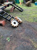
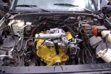
An air compressor mounted along side the the drop box can be run easily with a pulley off the stub shaft from the drop box...
A re-purposed crank shaft pulley and a tad bit of machining can easily get the compressor capable of operating at drive shaft speed.
Slow crawling may not do all we need in the way of providing air, but it will sure help when traveling at any speed.
The electric pumps are going to be the backbone of the air system though....
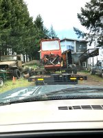
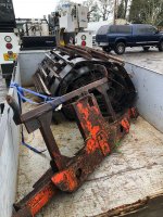
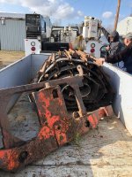
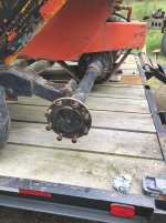
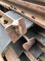
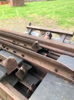
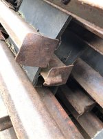
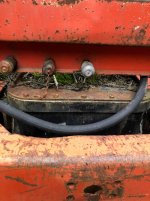
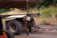
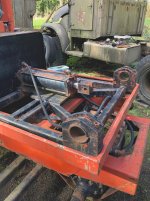
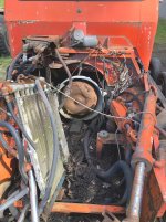
Here is a piccy of the 241 case sitting just about in the position it will be when it is finished.
Case will be run in the 4H position to engage the front flange. (There will be no low range, as this is only between the input and outputs with the original design...we are simply using the box to transmit power through and drop the elevation)
Yes...all the power will pass through the chain in the 241
After doing some serious checking on what that chain can handle power wise...and speaking to one of the major case builders...
It was determined that there are other places in the system that could likely be "A FUSE" before the chain goes away..
The 241 cases have been beaten horribly over the decades by many off road freaks with huge engines and they have lived well...sooooooooooooo I believe that the little Chevy V6 will likely not break too much....at least not without someone getting insane with things.
Many hours spent looking at the various concepts and going over the engineering.
Will this thing work ????? MAYBE...IT SHOULD