• Please be sure to read the rules and adhere to them. Some banned members have complained that they are not spammers. But they spammed us. Some even tried to redirect our members to other forums. Duh. Be smart. Read the rules and adhere to them and we will all get along just fine. Cheers. :beer: Link to the rules: https://www.forumsforums.com/threads/forum-rules-info.2974/

OC-12 parts

fischerrc4

New member
Hi Pat,
Have you seen Roller Bearings in the OC-12 drop boxes in your travels? That is what are in mine, and they are the Max Type bearing. I belive I may have purchased the last 8, american made (Bower), in the country. If anyone would like to see photos, I can post them this week-end.
They look tough !
 

Snowcat Pat

Active member
I'm back. We had 3 feet of fresh so I had to go get some. Only my fourth snowboard day this season. So after the snow laden tree fell on our woodshed, crushed it, and buried all our firewood, and we quickly went out to cut and split a new supply (whew), I really needed to get away.

Yes I would like to see the DB roller bearing setup. I haven't seen that before. I wonder if it came from the factory that way. What is the bearing number? I'd like to see if they are the same size as the ball bearings normally there. It might prevent something like this.............

-Pat
 

Attachments

  • 3375 blown upper DB bearing.JPG
    3375 blown upper DB bearing.JPG
    96.3 KB · Views: 403

fischerrc4

New member
3 Feet, Wish It fell in WA State! The Bearings are "Bower MU1014's" I can get the race part number for you this week, and more photos of the races in the cases.
I'll contact you this week for a parts order.
 

Attachments

  • Bower.jpg
    Bower.jpg
    45.4 KB · Views: 384

fischerrc4

New member
Pat,
Have you ever enlarged the Compensating Pinion Gear holes so you could use modern sized Dimple Bushings? They make some real nice 1" I.D. bushings.
 

Snowcat Operations

Active member
SUPER Site Supporter
Well today I just picked up a ring and pinion set for my OC-12 The gear ratio is 4.47! I also picked up a set of the 1.83 drop down gear sets. Does anyone know how to calculate the top speed with these new gear ratios? I could do it with a car but not sure how to with a snowcat........
 

Snowcat Operations

Active member
SUPER Site Supporter
Im guessing about a 18 to 21 mph top speed range. This sure would help getting in and out in the same day to our sites.
 

Snowcat Pat

Active member
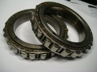
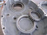
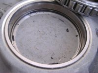
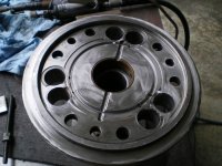
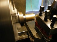
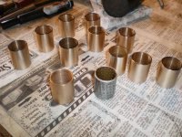
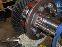
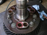
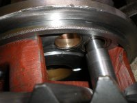
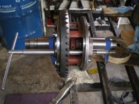
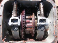
fischerrc4, I like the dimple bushings too, they are steel backed and seem to press in a little more securely. That said, I am very reluctant to modify the basic structure or dimensions of the original parts so over-boring the comp pinion holes isn't something I would normally do. Trying to maintain the original spec wherever I can so someone working on them later won't have a difficult time at it. None of our supplier provide the OEM dimple bushings for that area but instead use all bronze bushings throughout. So thats what we use now too. My next photos for this show and tell will be the fitting and line reaming of the bushings in question.

Snocat Ops, great news, I haven't heard of or seen 4.47 R&P gears before Something to consider is that the Drop Box gears provide extra steering leverage over straight axle (non-drop box like Super Imp) so it follows that the 2.44 DB's have more steering leverage than the 1.83 DB's do. Theoretically the combo of your 4.47 R&P with the commonly available 2.44 DB's would have both speed and ease of steering. That is with all other things being equal i.e; 12 tooth sprocket and same track width and style etc. Its much easier though, to change DB gears than to change the R&P

Here What I get calculating from the chart. Someone should check my math though.
For 3000 RPM engine speed.

4.47/R&P, 2.44/DB, total ratio/10.91, axle rpm/275, speed/12.5 mph

4.47/R&P, 1.83/DB, total ratio/8.18, axle rpm/301, speed/16.68mph


Also keep in mind that the higher ratios may have you driving the auto trans in first gear for long periods of time when climbing in the deep stuff.
-Pat
 

Snowcat Operations

Active member
SUPER Site Supporter
Found these beauties today.
 

Attachments

  • OC12 001.jpg
    OC12 001.jpg
    171.1 KB · Views: 336
  • OC12 002.jpg
    OC12 002.jpg
    205.8 KB · Views: 337
  • OC12 004.jpg
    OC12 004.jpg
    150.7 KB · Views: 323
  • OC12 005.jpg
    OC12 005.jpg
    153 KB · Views: 321

fischerrc4

New member
As promised, photos of the MU1014 Drop Box Roller Bearings, and Change that Oil.
 

Attachments

  • MU1014-3.jpg
    MU1014-3.jpg
    71.8 KB · Views: 269
  • Bad Things.jpg
    Bad Things.jpg
    71.1 KB · Views: 275
  • MU1014-2.jpg
    MU1014-2.jpg
    68.8 KB · Views: 270
  • MU1014-1.jpg
    MU1014-1.jpg
    71 KB · Views: 272

Snowcat Pat

Active member
I'm curious as to how those roller bearings will take care of the end play. In other words, the side to side motion of the gears. Ball bearings handle that by design but cylindrical roller bearings usually have no provision for controlling axial movement.

Anyway, here is a pic of the finished repair the gouged comp cover. The comp cover metal is a very weldable cast steel so I use heliarc and mild steel rod, rather than nickel or stainless. Mild steel rod lessens the chance of flaking that sometimes occurs when welding with dissimilar metals. I only repair three pinion holes on each comp cover since thats all thats needed. This cover has been flipped once already so welding is the only repair option other than machining the entire face, witch would mean removing about .080 inch in this example.

The second pic is what I do to the axle gear instead of machining that additional groove in the face of the comp cover. I deburr them like I've done the internal comp pinions.

The addition of that groove greatly accelerates the wear of the comp cover, so I think it is a bad idea. All the welding required to remove it might warp the cover, but machining it flat would require adding quite a bit of shim pack under the carrier bearings which would mean starting from scratch with the R&P alignment. Also the case width numbers marked on the ring gear would be meaningless. If it were my own machine or if the customer wanted it I would probably go ahead and machine out that wide groove and deal with the hassle of extra shims and realignment. In that case it might be possible to not weld the pinion holes at all. If I'm changing the ring gear the case width numbers marked on it don't matter anyway. Also there would be an opportunity to improve the ring gear runout while machining that face (or making it worse which is why I'm hesitant to do it).

-Pat
 

Attachments

  • 3572 welded repair of comp cover.JPG
    3572 welded repair of comp cover.JPG
    74.7 KB · Views: 240
  • 3592 deburred axle gear teeth.JPG
    3592 deburred axle gear teeth.JPG
    45.3 KB · Views: 239

Snowcat Pat

Active member
The internal comp pinion bushings I use are a bit oversize on the OD and undersize on the ID which is great because I can make the fit perfect.

The first pic is machining the OD.

The second pic show a group of bushings. In the the foreground left is an un-machined bushing and the foreground right is an OEM steel backed dimple bushing. The rest of them are machined and ready to install.

Of our two sources of bushings, the ones shown are from the "Z" store.

If you want to avoid machining you can get bushings from the "P" store and they will have the correct press fit but be quite oversize on the bore, so much so that you may have been better off not to change them at all. They also cost four times as much.

Neither suppliers have the steel backed dimple bushings.

-Pat
 

Attachments

  • 3532 smaller press fit needed.JPG
    3532 smaller press fit needed.JPG
    53 KB · Views: 233
  • 3526 bushings old and new.JPG
    3526 bushings old and new.JPG
    98.2 KB · Views: 230

Snowcat Pat

Active member
Here is the line reaming step of internal comp pinion bushings. This is a full mornings work to do it well. I will make 20 or more passes through each bushing taking about .0002 inch with each pass, thats just the way adjustable reamers work, otherwise the finish suffers with scoring or gouging. Done carefully an adjustable reamer makes a very smooth finish.

The handle of the reamer holder removes so that the tool can be PULLED though to maintain alignment with its opposite bushing. The pics show how the body of the reamer holder pilots on the opposite bushing for near perfect alignment.

My tips are to use liberal (theres that word again) amounts of Rapid Tap cutting fluid. Another good fluid is Tapmatic, really good stuff if you don't mind the fumes. I suppose Rigid Pipe Threading oil might be good too but I don't use that high sulphur stuff anymore, bad for the hands, throat and lungs.

NEVER turn the reamer counterclockwise. Never move it at all unless turning it clockwise at the same time. If it gets stuck you took too big of a bite, and it will leave a scar. Patience is the key.

The manual spec's a clearance of .004 inch and I go to just that amount. Tighter would be nice but if any of the bushings in the diff should bind it could spin and thats really bad.

You have to measure the internal comp pinion shafts determine the actual size to ream their bushings. Most of the time a set of six pinions will all have the same amount of shaft wear and all the bushings can be reamed to the same size. If you are replacing a pair of pinions then you have to keep track of them and their respective bushing locations. I usually keep all the pinions in their original locations.

Thats this weeks contribution.

-Pat
 

Attachments

  • 3625  line ream starting position.JPG
    3625 line ream starting position.JPG
    77.1 KB · Views: 247
  • 3689 comp cover nearly finished.JPG
    3689 comp cover nearly finished.JPG
    65.1 KB · Views: 242
  • 3675 fresh glowing bronze.JPG
    3675 fresh glowing bronze.JPG
    76.6 KB · Views: 236
  • 3628 shank guides reamer .JPG
    3628 shank guides reamer .JPG
    62.5 KB · Views: 239
  • 3623 setup to line ream bushings.JPG
    3623 setup to line ream bushings.JPG
    74 KB · Views: 253

fischerrc4

New member
Hi Pat,
You have brought up a interesting topic. The bearings are MU1014DAL's. I am told they make three types. The DAL bearings have a lip on the races, and the taper, to support the Axial Loads. The races are set to the bottom of the cases, so no movement is possible. Preload is adjusted with the differential shims, just like the ball bearings. On the outboard sides, they rest on the axle tubes themselves. I guess you could shim the axle tubes if needed. This is my first rebuild of an OC-12, so I have alot to learn. I will take lots of photos during my assembly, and there will be plenty of questions to be answered.
I will get to the shop this week, and get the exact bearing/ race part numbers for all.
I do not have all the answers yet, but I will, before I finish.
fischerrc4
 

fischerrc4

New member
Well after a mad dash to the shop to reboot computers after a power outage. I have returned with the Bearing Part Numbers. The races are, Bower M-1014-DA, and the Roller Bearings are, Bower MU-1014-L. As a set they are, Bower M-1014-DAL.
I was told I may have purchased the last 8 AMERICAN made in the U.S. So good luck finding a set of 8.
If any additional photos are needed let me know.
Much more to come,
fischerrc4
 

fischerrc4

New member
The Manufacturer states the Application as follows:
1) Takes moderate thrust loads or locates shaft in one direction only.
2) When used in pairs on common shaft, thrust loads can be taken or shaft located in either direction.
Should be interesting.
 

Snowcat Operations

Active member
SUPER Site Supporter
Inside my OC12. She looks recently rebuilt with new brake bands ect.
 

Attachments

  • OC12 009.jpg
    OC12 009.jpg
    188.3 KB · Views: 177
  • OC12 010.jpg
    OC12 010.jpg
    181.6 KB · Views: 174
  • OC12 011.jpg
    OC12 011.jpg
    188.6 KB · Views: 169
  • OC12 012.jpg
    OC12 012.jpg
    171 KB · Views: 170
  • OC12 013.jpg
    OC12 013.jpg
    160.9 KB · Views: 174
  • OC12 014.jpg
    OC12 014.jpg
    133.6 KB · Views: 172

Snowcat Operations

Active member
SUPER Site Supporter
Last ones. I will install a new set of ring and pinion gears and then put her up for sale if anyone is interested. PM me.
 

Attachments

  • OC12 015.jpg
    OC12 015.jpg
    154.8 KB · Views: 168
  • OC12 016.jpg
    OC12 016.jpg
    198.8 KB · Views: 170
  • OC12 017.jpg
    OC12 017.jpg
    155.4 KB · Views: 168
  • OC12 018.jpg
    OC12 018.jpg
    163.8 KB · Views: 172
  • OC12 019.jpg
    OC12 019.jpg
    187.2 KB · Views: 168

Snowcat Operations

Active member
SUPER Site Supporter
I would like to cut out a new gasket out of 1/8 rubber gasket material. Would this work good? I can have some cut out on a very precise cutting machine. They would be a one piece design.
 

Snowcat Operations

Active member
SUPER Site Supporter
She is currently sporting a 4.08 gear set! According to Snowcat Pat this is a rare bird indeed. I will be putting my original 6.14 Ring and Pinion set in this straight axle OC12. I'm guessing at about a 22.93 mph top speed at 3,000 rpms with the new gear set in her. Not sure. Snowcat Pat what do you think the top speed will be with the new gear set in her?
 
Top